There are many different types of robot projects that you might be aware of including the following:
- Remote-controlled robot (car type 3/4-wheeler)
- Joystick controlled robot
- Gesture controlled robot
- Smartphone (Bluetooth) controlled robot
- Obstacle avoidance robot
- Object follower robot
- Object finder robot
- Robotic Arm
- Pick and place robot
- And many more
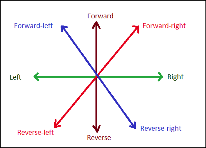
This article also describes a robot whose distinct feature is in its name. It’s an omnidirectional robot meaning it can move in any of the eight directions, as well as forward-reverse-left-right—as shown in the figure, with the ability to rotate clockwise and counterclockwise on its central axis.
This unique feature of such a robot finds its applications in many different fields, including:
- Material handling robot – in huge FMCG manufacturing industries, large department stores, packaging industries, massive warehouses, such robots can be used to move items from one place to another
- Floor cleaning robot – such robots can be used to clean the floor or flat surface
- Agriculture robot – this type of robot can be used in farms for pulling out weeds or reaping the crops
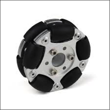
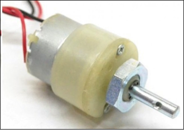
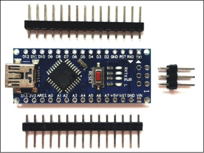
This article describes the design and development of an omnidirectional robot. The robot is built using particular types of wheels known as mecanum wheels (popularly known as omnidirectional wheels), Arduino NANO board, and DC gear motors. A smartphone controls the robot through Bluetooth.
List of required items and components
- Omnidirectional wheels
- DC gear motors with 200 or 300 RPM
- 12 V @ 2 A Battery (Lead Acid type)

- Arduino NANO development board
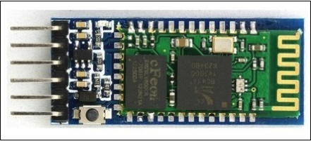
- Bluetooth module HC-05 (or HC-06)
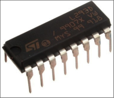
- Motor driver chip L293D
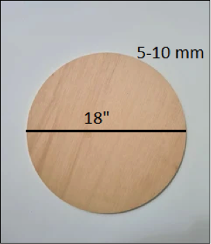
- The round wooden base of 18” diameter and 5mm to 10 mm thick
First, we’ll see how to build a robot, and then we shall build the circuit
Building an omnidirectional robot
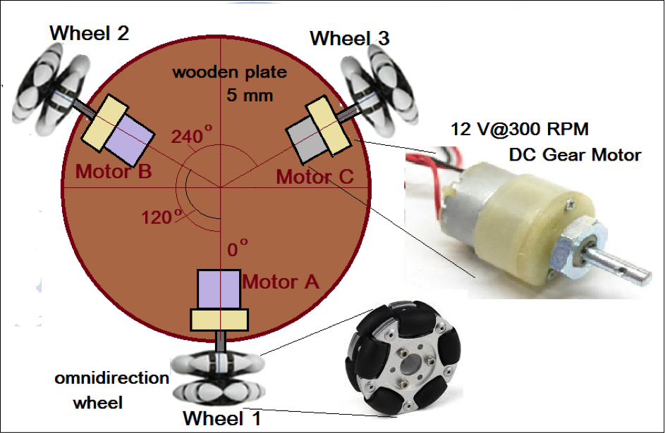
The figure shows that the robot is like a round wooden plate with three omnidirectional wheels attached to three different DC motor shafts, which are fixed to the bottom side of the wooden plate using clamps at a specific angle.

All three motors are fixed at an angle of 120o apart from each other. Omnidirectional wheels are attached to the DC motor shaft directly using a given screw in the motor shaft. Now, our omnidirectional robot is ready— and ready to move in any direction.
How can this simple round plate type robot with three motors and three wheels move in any direction? The figure below explains the robot movement in six different directions and its clockwise and counterclockwise rotations in eight different figure sections.
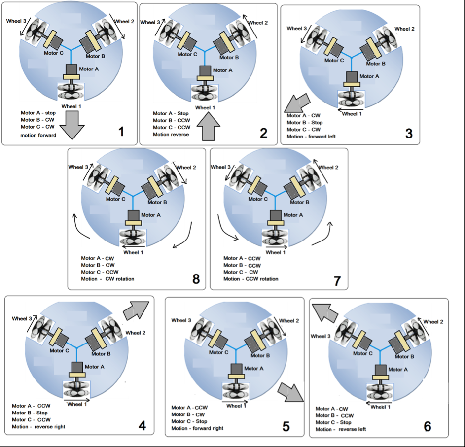
For example, as shown in figure section 1, when motor A is stopped, and motor B and motor C rotate clockwise (CW), the robot moves forward because the omnidirectional wheel attached with motor A will give free movement.
Similarly, as shown in section 2, the robot moves reverse by keeping motor A stop and rotating motor B and C counterclockwise (CCW).
Thus by keeping any one motor stop and rotating the other two motors, we can move the robot forward-left, reverse-right, forward-right, and reverse-left. This is shown in sections 3, 4, 5 and 6.
Sections 7 and 8 show how the entire robot rotates in CW and CCW direction. For this, all three motors have to rotate, but two motors will rotate in the same direction (motor A and B) while one motor will rotate in another direction (motor C)
Now let us move on to the next stage and build the circuit that will rotate these three motors, CW (forward) and CCW (reverse), as per the desired robot movement
Circuit diagram and connections
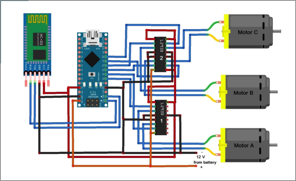
As shown in the figure, the circuit is built using only three components: Arduino NANO development board, Bluetooth module HC05, and motor driver chips L293D.
- The HC05 module has four interfacing pins. (1) Vcc, (2) Gnd, (3) Rx, and (4) Tx. Its Vcc pin is given 5 V supply from Arduino 5 V, and ground pin is connected with circuit ground. Its Tx pin is connected with Rx pin (D0) of Arduino board, and Rx pin is connected with Tx pin (D1)
- Two motor driver chips L293D drives 3 DC motors. Arduino board digital pins D3 to D8 are used to drive motor A, motor B, and motor C

- The Arduino board is given a 12 V supply from the battery. Both motor driver chips are also given a 12 V supply at pin 8 for motors. L293D chips also require 5 V biasing voltage.
This circuit can be easily built on a general-purpose PCB or even on a breadboard.
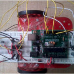
Here is the snapshot of the robot with the circuit.

Circuit working and operation
- The HC05 module gets a command from the user’s smartphone through the Bluetooth Android app. It then sends this command to the Arduino board serially using Tx and Rx pins.
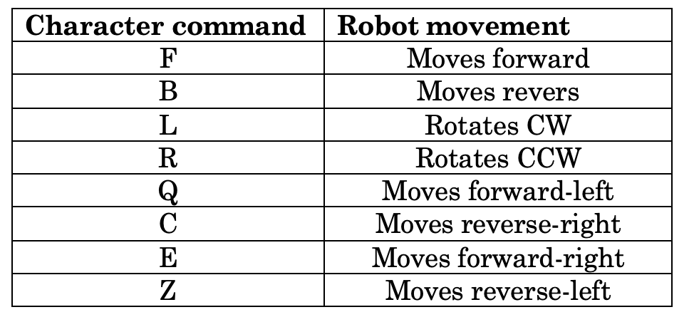
- When the Arduino board gets a command from the HC05 module, it will rotate all three motors forward or reverse as per the following table to move the robot in the desired direction. Arduino drives all three motors using L293D chips.

How to control robot motion (movement)
- To control robot motion and to move the robot in any desired direction, the user has to send commands from his smartphone through the Bluetooth Android app.
- The phone searches for the HC05 module, and when found, it asks the user to make a pair. First-time pairing requires default HC05 module passkey that is “1234”. The user has to enter the passkey from his smartphone and make a pair with the HC05 module.
- The user has to open a Bluetooth controlling Android app on his phone (like a Bluetooth terminal). The application asks to connect with a Bluetooth device. You then select the HC05 module and establish a connection with it.
- Finally, we are ready to send commands to move the robot using the ollowing character commands to move the robot in different directions
The robot movements depend on the software program downloaded into the Arduino board microcontroller, ATMega328. The circuit and the robot’s complete working and operation are as per the software program. Robots move for one or two seconds and stop automatically. To move the robot, the user has to use a smartphone as a joystick.
Now, let us see this software program that is downloaded into internal FLASH of Arduino board microcontroller (ATMega328)
Software Program
The AATMega328 performs the following tasks per the programming:
- Gets command serially from HC05 module using Tx-Rx pins
- Drives and rotates all 3 DC motors forward and reverse by sending High / Low logic to digital pins D3 to d8
- Rotates all 3 DC motors in the proper direction to move the robot in the exact direction as per the user command
The program is written in C/C++ language using Arduino IDE software. It is also compiled and uploaded into Arduino board micro-controller using the same software
Here is the program.
Here is the youtube video link for this project
You may also like:


Filed Under: Electronic Projects, Featured

Questions related to this article?
👉Ask and discuss on Electro-Tech-Online.com and EDAboard.com forums.
Tell Us What You Think!!
You must be logged in to post a comment.