Engineers Garage

  • Projects and Tutorials
    • Electronic Projects
      • 8051
      • Arduino
      • ARM
      • AVR
      • PIC
      • Raspberry pi
      • STM32
    • Tutorials
    • Circuit Design
    • Project Videos
    • Components
  • Articles
    • Tech Articles
    • Insight
    • Invention Stories
    • How to
    • What Is
  • News
    • Electronic Products News
    • DIY Reviews
    • Guest Post
  • Forums
    • EDABoard.com
    • Electro-Tech-Online
    • EG Forum Archive
  • Digi-Key Store
    • Cables, Wires
    • Connectors, Interconnect
    • Discrete
    • Electromechanical
    • Embedded Computers
    • Enclosures, Hardware, Office
    • Integrated Circuits (ICs)
    • Isolators
    • LED/Optoelectronics
    • Passive
    • Power, Circuit Protection
    • Programmers
    • RF, Wireless
    • Semiconductors
    • Sensors, Transducers
    • Test Products
    • Tools
  • EE Resources
    • DesignFast
    • LEAP Awards
    • Oscilloscope Product Finder
    • White Papers
    • Webinars
  • EE Learning Center
    • Design Guides
      • WiFi & the IOT Design Guide
      • Microcontrollers Design Guide
      • State of the Art Inductors Design Guide
  • Women in Engineering

SMD Resistors

By D.Mohankumar

 SMD resistors are small rectangular shaped components with metalized areas at the ends. The metalized areas are used for soldering with the PCB. The SMD resistor has ceramic substrate on to it a metal oxide film is deposited. The thickness and length of this metal oxide film determines the value of resistance. The use of Metal oxide gives good stability and tolerance to the SMD resistors.Unlike color coded resistors, SMD resistors do not have any color bands instead they have numbers printed on it. It is difficult to identify the SMD resistor if the coding method is not known. Here describes the methods to identify the SMD Resistor.

SMD Resistor
 
The SMD resistors are available in different packages. Commonly available packages are 2512, 2010,1812,1210,1206,0805,0603,0402,021 etc. These packages are based on the size of the resistor ranging from 6.30×3.10 to 0.6×0.3 mm. Power rating and tolerance also vary depending on the make.
 
Marking system
SMD Resistor marking system is mainly used for the replacement of the resistor or fault finding. Many SMD resistors do not have marks on it so that it is difficult to identify them. But some have marks printed on the body for easy identification. There are three marking systems commonly used.
 
SMD Resistor Marking
 
 
[header = Three Figure Marking]
 
Three figure marking
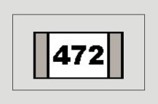
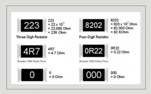
In 3 figure marking, there are three figures. The first and second figures indicate the significant figures and the third one, is the multiplier. Instead of the color rings, actual number is used in figures. For example, if the SMD resistor has the figures 472, it indicates 4, 7 = 47 x 102 ohms. That is the value is 4.7K.But the resistors marked as 100 is not a 100 ohm resistor but 10×100 = 10 ohms or 10×1 = 10 ohms. In the case of resistors less than 10 ohms, the letter R is used in the position of decimal. For example, 5R6 represents 5.6 Ohms.
 
3-digit code examples:
220 = 22 × 100 (1) = 22O (not 220O!)
471 = 47 × 101 (10) = 470O
102 = 10 × 102 (100) = 1000O or 1kO
3R3 = 3.3O
 
 
[header = Four Figure Marking]
 
Four figure marking
4 Digit markings are used to denote high tolerance SMD resistors. In these resistors, the first, second and third figures represent significant values while the fourth is the multiplier. For example, if the figures are 4702 then the value is 470 x 102 ohms or 47K. In 4 figure marking, the values less than 100 ohms use the letter R at the position of the decimal point.
 
4-digit code examples:
4700 = 470 × 100 (1) = 470O (not 4700O!)
2001 = 200 × 101 (10) = 2000O or 2kO
1002 = 100 × 102 (100) = 10000O or 10K?
15R0 = 15.0O

SMD Resistors
 
 
[header = EIA 96 Marking]
 
EIA 96 marking
EIA 96 marking system is used in resistors with 1% tolerance. In this marking, three character code is used. First and second digits indicate the resistor value and the third character is a letter that indicates the multiplier. For example if the marking is 68X, then X represents 0.1. Figures 68 X can be split into two elements. 68 represent significant figures 499and X represents 0.1. So the value is 499×0.1 = 49.9 ohms.
 
Other markings include Z(0.001),Y or R(0.01),X or S(0.1),A(1),B or   H(10),C(100),D(1000),E(10,000),F(1,00000) etc.
 
EIA-96 code examples:
01Y = 100 × 0.01 = 1O
68X = 499 × 0.1 = 49.9O
76X = 604 × 0.1 = 60.4O
01A = 100 × 1 = 100O
29B = 196 × 10 = 1.96kO
01C = 100 × 100 = 10kO
 
 
[header = Other Markings]
 
Other markings on SMD Resistor
1. SMD resistor with a marking of 0, 00, 000 or 0000 is a jumper or zero ohm link.
2. The SMD  resistor marked with the standard 3 digit code and a short bar below the marking denotes a precision of 1% or less .For example: 122 = 1.2kO 1%.
3. SMDs resistors in order of milliohms, made for current sensing applications are often marked with a letter M or m, showing the decimal point location. For example: 1M50 = 1.50mO
4. SMD resistors in current sensing property can also be marked with a long bar on top .For example 1m5 = 1.5mO, R001 = 1mO, etc. or a long bar under the code .For example 101 = 0.101O, 047 = 0.047O. The underline is used when the starting ‘R’ has to be omitted due to the limited space on the resistor’s body.


Filed Under: Electronic Projects


Questions related to this article?
👉Ask and discuss on EDAboard.com and Electro-Tech-Online.com forums.


Tell Us What You Think!! Cancel reply

You must be logged in to post a comment.

HAVE A QUESTION?

Have a technical question about an article or other engineering questions? Check out our engineering forums EDABoard.com and Electro-Tech-Online.com where you can get those questions asked and answered by your peers!


Featured Tutorials

  • Introduction to Brain Waves & its Types (Part 1/13)
  • Understanding NeuroSky EEG Chip in Detail (Part 2/13)
  • Performing Experiments with Brainwaves (Part 3/13)
  • Amplification of EEG Signal and Interfacing with Arduino (Part 4/13)
  • Controlling Led brightness using Meditation and attention level (Part 5/13)
  • Control Motor’s Speed using Meditation and Attention Level of Brain (Part 6/13)

Stay Up To Date

Newsletter Signup

Sign up and receive our weekly newsletter for latest Tech articles, Electronics Projects, Tutorial series and other insightful tech content.

EE Training Center Classrooms

EE Classrooms

Recent Articles

  • Key factors to optimize power consumption in an embedded device
  • EdgeLock A5000 Secure Authenticator
  • How to interface a DS18B20 temperature sensor with MicroPython’s Onewire driver
  • Introduction to Brain Waves & its Types (Part 1/13)
  • An Embedded Developer’s Perspective on IOT (Internet of Things)

Most Popular

5G 555 timer circuit 8051 ai Arduino atmega16 automotive avr bluetooth dc motor display Electronic Part Electronic Parts Fujitsu ic infineontechnologies integratedcircuit Intel IoT ir lcd led maximintegratedproducts microchip microchiptechnology Microchip Technology microcontroller microcontrollers mosfet motor powermanagement Raspberry Pi remote renesaselectronics renesaselectronicscorporation Research samsung semiconductor sensor software STMicroelectronics switch Technology vishayintertechnology wireless

RSS EDABOARD.com Discussions

  • Dynamic power consumption.
  • Limits of duty cycle for ICM7555 IC?
  • pmos folded cascode vs nmos folded cascode for LDO
  • Pic 16f877A Hex file
  • Need help to choose accelerometer

RSS Electro-Tech-Online.com Discussions

  • Help wanted to power an AC120v induction motor ( edited from Brushless motor - thank you @SHORTBUS= )
  • How does a NOAC work?
  • Need help working with or replacing a ferrite tube
  • Trying to make a custom automated water container for my UV purifier. Can anyone help with where to begin?
  • Funny Images Thread!
Engineers Garage
  • Analog IC TIps
  • Connector Tips
  • DesignFast
  • EDABoard Forums
  • EE World Online
  • Electro-Tech-Online Forums
  • Microcontroller Tips
  • Power Electronic Tips
  • Sensor Tips
  • Test and Measurement Tips
  • 5G Technology World
  • About Us
  • Contact Us
  • Advertise

Copyright © 2022 WTWH Media LLC. All Rights Reserved. The material on this site may not be reproduced, distributed, transmitted, cached or otherwise used, except with the prior written permission of WTWH Media
Privacy Policy | Advertising | About Us

Search Engineers Garage

  • Projects and Tutorials
    • Electronic Projects
      • 8051
      • Arduino
      • ARM
      • AVR
      • PIC
      • Raspberry pi
      • STM32
    • Tutorials
    • Circuit Design
    • Project Videos
    • Components
  • Articles
    • Tech Articles
    • Insight
    • Invention Stories
    • How to
    • What Is
  • News
    • Electronic Products News
    • DIY Reviews
    • Guest Post
  • Forums
    • EDABoard.com
    • Electro-Tech-Online
    • EG Forum Archive
  • Digi-Key Store
    • Cables, Wires
    • Connectors, Interconnect
    • Discrete
    • Electromechanical
    • Embedded Computers
    • Enclosures, Hardware, Office
    • Integrated Circuits (ICs)
    • Isolators
    • LED/Optoelectronics
    • Passive
    • Power, Circuit Protection
    • Programmers
    • RF, Wireless
    • Semiconductors
    • Sensors, Transducers
    • Test Products
    • Tools
  • EE Resources
    • DesignFast
    • LEAP Awards
    • Oscilloscope Product Finder
    • White Papers
    • Webinars
  • EE Learning Center
    • Design Guides
      • WiFi & the IOT Design Guide
      • Microcontrollers Design Guide
      • State of the Art Inductors Design Guide
  • Women in Engineering