Engineers Garage

  • Projects and Tutorials
    • Electronic Projects
      • 8051
      • Arduino
      • ARM
      • AVR
      • PIC
      • Raspberry pi
      • STM32
    • Tutorials
    • Circuit Design
    • Project Videos
    • Components
  • Articles
    • Tech Articles
    • Insight
    • Invention Stories
    • How to
    • What Is
  • News
    • Electronic Products News
    • DIY Reviews
    • Guest Post
  • Forums
    • EDABoard.com
    • Electro-Tech-Online
    • EG Forum Archive
  • Digi-Key Store
    • Cables, Wires
    • Connectors, Interconnect
    • Discrete
    • Electromechanical
    • Embedded Computers
    • Enclosures, Hardware, Office
    • Integrated Circuits (ICs)
    • Isolators
    • LED/Optoelectronics
    • Passive
    • Power, Circuit Protection
    • Programmers
    • RF, Wireless
    • Semiconductors
    • Sensors, Transducers
    • Test Products
    • Tools
  • EE Resources
    • DesignFast
    • LEAP Awards
    • Oscilloscope Product Finder
    • White Papers
    • Webinars
  • EE Learning Center
    • Design Guides
      • WiFi & the IOT Design Guide
      • Microcontrollers Design Guide
      • State of the Art Inductors Design Guide
  • Women in Engineering

Speed Control of DC Motor Using PID Method

By Ankit Patel


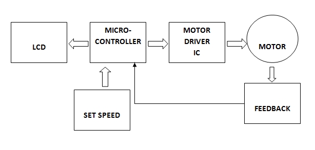
The development of high performance motor drives is very important in industrial as well as other purpose applications. Generally, a high performance motor drive system must have good dynamic speed command tracking and load regulating response. The dc motors are used in various applications such as defense, industries, Robotics etc. DC drives, because of their simplicity, ease of application, reliability and favorable cost have long been a backbone of industrial applications. The project provides the efficient and simple method to control speed of DC motor using ATMEGA16 microcontroller and L298N motor driver IC. 

DC MOTOR

With the use of ATMEGA16 and l298N we can drive the dc motor at desired speed having a feedback loop and in this project we have used proportional integral and derivative method in which errors are not only solved but also taken to its minimal value with very low amount of error oscillations.

PROPORTIONAL CONTROL:

The proportional part of PID examines the magnitude of the error and it reacts proportionally. A large error receives a large response

INTEGRAL CONTROL:

To address the first issue with the proportional control, integral control attempts to correct small error (offset).

DERIVATIVE CONTROL:

The derivative part of the control output attempts to look at the rate of change in the error signal. Derivative will cause a greater system response to a rapid rate of change than to a small rate of change.

WORKING OF PROJECT

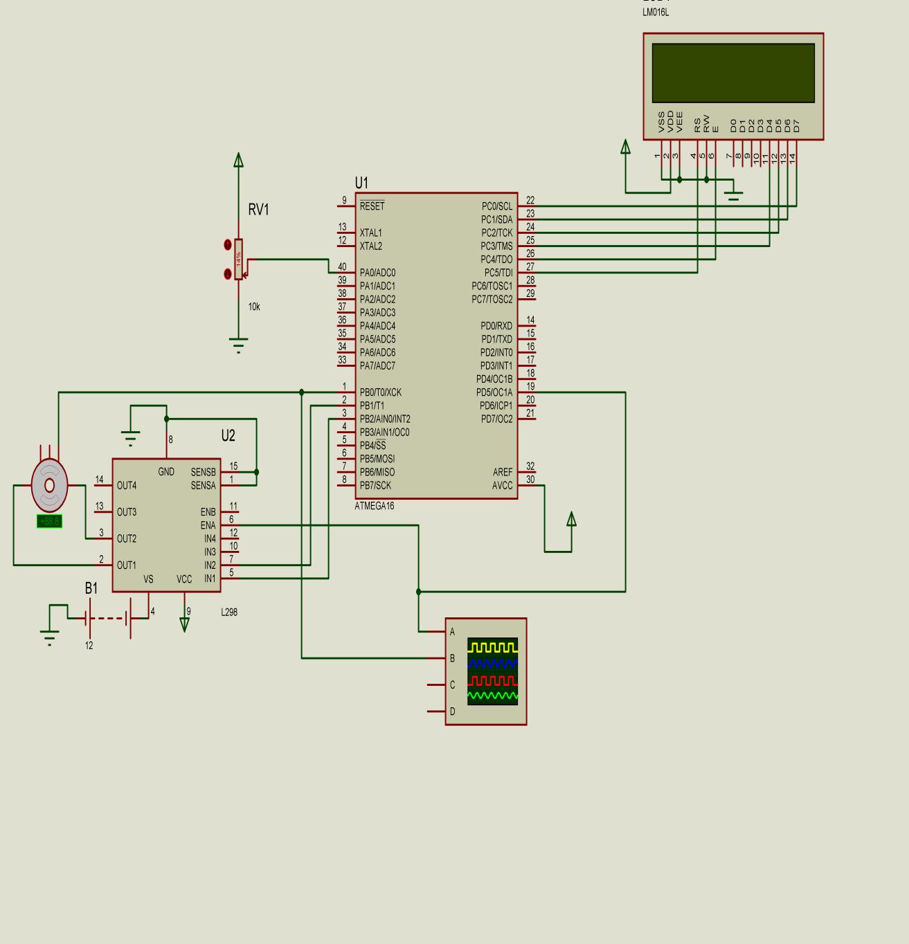
First the speed of the dc motor connected is set with the help of a variable resistance of 10k which is connected to A0 pin which works as ADC port in the microcontroller. As the controller gets the speed set by the user it starts counting the pulse which it is getting from a CMOS sensor and on the basis of that it measures the current speed of motor.After that the user entered speed and the current speed of the motor is compared and the difference is calculated as error and in accordance to that error the pwm signal given to the L298n IC for driving motor through microcontroller is varied.

First of all IC L298N is used to drive the motor in which two pins are used as output for the motor driving and the enable pin in the IC is supplied by the PWM signals from the microcontroller ATMEGA16. By supplying high to the enable1 pin on the IC L298N the IC provides the 12V supply to the motor so by varying the signal to the enable pin we can easily vary the speed of the motor. By increasing the time of on period in the duty cycle of PWM signal the speed of the motor can be increased and vice versa.
Now as shown in the circuit diagram above ENA is connected with pin19 of the microcontroller which serves as the output pin for the internal PWM function of the ATMEGA16. Internal PWM of the microcontroller is used because it does not generate any delay in the execution of code of program whereas if PWM is generated in programming is used than it may cause delay in execution. A 10K potentiometer is connected to port A pin A.1 which serves as a ADC port and by varying the value of resistance the value of supply given to the pin A.1 varies smoothly between 0 to 5V and therefore it works as input speed of the motor. Now when power supply is switched on user has to set a desired speed using potentiometer and after getting the speed from user motor starts rotating. As rotating disc is connected to the shaft of the motor it will work as tachometer with the combination of CMOS sensor. There are 24 holes in the disc which allows the rays to pass through it in the CMOS sensor and the sensor is connected to the pin B.0 which works as the counter i.e. whenever it receives high signal it increments its counter value by 1 and therefore we get to know how many number of holes have been pass through the sensor in a particular time period.
Now by simply using the formula written in program the number of counts is converted into the rotation per minute of the motor. That rpm value is stored in a variable and that variable is now compared with the user set speed.The difference we got is counted as error and from now onwards PID calculation starts in the program.
Error = Set_rpm – Feedback_rpm
This is the proportional error which is the direct error that we got from the subtraction of the set rpm value and feedback rpm value.
             H = Error * Dt
             I_error = I_error + H
This is the integral error part in which previous errors are also added to minimize the error in the actual quantity and take the actual value to the true value or required value.
  I = Error – Previous_error
             D_error = I / Dt
This is the derivative error which is used to decrease the oscillations in the value of the speed of the motor.
             J = P_gain * Error
             K = I_gain * I_error
             L = D_gain * D_error
             M = J + K
             Otpt = M + L
Now all three errors are multiplied by their gain constants which are set manually with motor characteristics and testing on motor. Now by adding all three errors we got the actual error quantity which is used to get the smooth speed control over motor.
Onn = Onn + Otpt
Onn is the variable which stores the value of on time period in the PWM signals generated by the microcontroller and hence by varying this variable we can vary the PWM signal generated by the microcontroller.
           If Onn > 254 Then
           Onn = 254
           End If
           Compare1a = Onn
Here if speed is maximum or tries to reach over its maximum value than onn has given the 254 value which indicates 100% on time period in PWM signals otherwise it is compared with the PWM signals i.e. it changes the on period of the PWM signal in accordance with the difference in onn and previous time period.Therefore the PWM signal varies and the speed of the motor varies and tries to reach the value set by the user and tries to dominate the error value and gives us the precise controlling over the motor.
DC MOTOR


Project Source Code


Project Source Code

###


$regfile "M16DEF.DAT"
$crystal = 8000000
$baud = 9600
$hwstack = 32
$swstack = 8
$framesize = 40
Config Timer1 = Pwm , Pwm = 8 , Compare A Pwm = Clear Up , Prescale = 8
Config Lcdpin = Pin , E = Portc.4 , Rs = Portc.5 , Db4 = Portc.3 , Db5 = Portc.2 , Db6 = Portc.1 , Db7 = Portc.0
Config Lcd = 16 * 2
Config Adc = Single , Prescaler = Auto , Reference = Avcc
Config Timer0 = Counter , Edge = Rising
On Ovf0 Tim0_isr
Enable Interrupts
Enable Timer0
Tcnt0 = 0
Config Portc = Output
Dim A As Integer
Dim B As Integer
Dim C As Integer
Dim D As Single
Dim E As Single
Dim F As Single
Dim G As Single
Dim H As Single
Dim I As Single
Dim J As Single
Dim K As Single
Dim L As Single
Dim M As Single
Dim X As Single
Dim Y As Single
Dim Errr As Integer
Dim Ad As Integer
Dim Onn As Integer
Dim P_gain As Single
Dim I_gain As Single
Dim D_gain As Single
Dim Dt As Single
Dim Set_rpm As Integer
Dim Previous_error As Single
Dim D_error As Single
Dim I_error As Single
Dim Error As Single
Dim Feedback_rpm As Integer
Dim Otpt As Integer
Set_rpm = 0
Previous_error = 0
D_error = 0
I_error = 0
P_gain = 0.65
I_gain = 0.005
D_gain = 0.005
Dt = 0.5
A = 0
B = 0
C = 0
D = 0
E = 0
F = 0
H = 0
G = 0
I = 0
J = 0
K = 0
L = 0
M = 0
X = 0
Y = 0
Otpt = 0
 Previous_error = Set_rpm - Feedback_rpm
Start Adc
Do
Set_rpm = Getadc(0)
Locate 2 , 1
Lcd Set_rpm
 Tcnt0 = 0
 Start Timer0
 Waitms 500
 Stop Timer0
 A = Tcnt0
 B = F * 255
 C = A + B
 D = C / 1
 E = D * 5
   E = E + 0
   G = E
  Feedback_rpm = G
  X = Set_rpm - 2
  Y = Set_rpm + 2
 If G > X And G < Y Then
    G = Set_rpm
 End If
 Cls
 Locate 1 , 1
 Lcd G
 F = 0
             Error = Set_rpm - Feedback_rpm
             H = Error * Dt
             I_error = I_error + H
             I = Error - Previous_error
             D_error = I / Dt
             J = P_gain * Error
             K = I_gain * I_error
             L = D_gain * D_error
             M = J + K
             Otpt = M + L
             Previous_error = Error
           ' Errr = Set_rpm - Otpt
           Onn = Onn + Otpt
           If Onn > 254 Then
           Onn = 254
           End If
           Compare1a = Onn
Loop
Tim0_isr:
F = F + 1
Return
End
Explanation of main course of program:
Config Timer1 = Pwm , Pwm = 8 , Compare A Pwm = Clear Up , Prescale = 8
Config Lcdpin = Pin , E = Portc.4 , Rs = Portc.5 , Db4 = Portc.3 , Db5 = Portc.2 , Db6 = Portc.1 , Db7 = Portc.0
Config Lcd = 16 * 2
Config Adc = Single , Prescaler = Auto , Reference = Avcc
Config Timer0 = Counter , Edge = Rising
On Ovf0 Tim0_isr
Timer 0 is configured as counter which counts the input pulse from the sensor.
Timer 1 is configured as PWM to give the output signal to the L298n.
Lcd and adc is also configured.
Start Timer0
 Waitms 500
 Stop Timer0
 A = Tcnt0
Timer is started to count the pulse for every 500 ms.
Value is stored into variable A.
A = Tcnt0
 B = F * 255
 C = A + B
 D = C / 1
 E = D * 5
   E = E + 0
   G = E
Conversion of pulses into rpm
  Feedback_rpm = G
  X = Set_rpm - 2
  Y = Set_rpm + 2
 If G > X And G < Y Then
    G = Set_rpm
 End If
 Cls
 Locate 1 , 1
 Lcd G
 F = 0
 Error = Set_rpm - Feedback_rpm
 H = Error * Dt
             I_error = I_error + H
             I = Error - Previous_error
             D_error = I / Dt
             J = P_gain * Error
             K = I_gain * I_error
             L = D_gain * D_error
             M = J + K
             Otpt = M + L
             Previous_error = Error
           ' Errr = Set_rpm - Otpt
           Onn = Onn + Otpt
 

###


Circuit Diagrams

circuit


Filed Under: Electronic Projects
Tagged With: dc motor, pid, speed control
 

Questions related to this article?
👉Ask and discuss on EDAboard.com and Electro-Tech-Online.com forums.


Tell Us What You Think!! Cancel reply

You must be logged in to post a comment.

HAVE A QUESTION?

Have a technical question about an article or other engineering questions? Check out our engineering forums EDABoard.com and Electro-Tech-Online.com where you can get those questions asked and answered by your peers!


Featured Tutorials

  • PS2 Keyboard To Store Text In SD Card Using Arduino Circuit Setup On Breadboard
    How To Use PS2 Keyboard To Store Text In SD Card Using Arduino- (Part 42/49)
  • Wireless Path Tracking System Using Mouse, XBee And Arduino Circuit Setup On Breadboard
    How To Make A Wireless Path Tracking System Using Mouse, XBee And Arduino- (Part 43/49)
  • How to Make a Wireless Keyboard Using Xbee with Arduino- (Part 44/49)
  • Making Phone Call From GSM Module Using Arduino Circuit Setup On Breadboard
    How to Make Phonecall From GSM Module Using Arduino- (Part 45/49)
  • How to Make a Call using Keyboard, GSM Module and Arduino
    How To Make A Call Using Keyboard, GSM Module And Arduino- (Part 46/49)
  • Receiving SMS Using GSM Module With Arduino Prototype
    How to Receive SMS Using GSM Module with Arduino- (Part 47/49)

Stay Up To Date

Newsletter Signup

Sign up and receive our weekly newsletter for latest Tech articles, Electronics Projects, Tutorial series and other insightful tech content.

EE Training Center Classrooms

EE Classrooms

Recent Articles

  • Renesas delivers intelligent sensor solutions for IoT applications
  • Microchip Technology releases AVR-IoT Cellular Mini Development Board
  • Qualcomm acquires Cellwize to accelerate 5G adoption and spur infrastructure innovation
  • MediaTek’s chipset offers high-performance option for 5G smartphones
  • Nexperia’s new level translators support legacy and future mobile SIM cards

Most Popular

5G 555 timer circuit 8051 ai Arduino atmega16 automotive avr bluetooth dc motor display Electronic Part Electronic Parts Fujitsu ic infineontechnologies integratedcircuit Intel IoT ir lcd led maximintegratedproducts microchip microchiptechnology Microchip Technology microcontroller microcontrollers mosfet motor powermanagement Raspberry Pi remote renesaselectronics renesaselectronicscorporation Research samsung semiconductor sensor software STMicroelectronics switch Technology vishayintertechnology wireless

RSS EDABOARD.com Discussions

  • Netlist physical name update
  • nt1065_USB3 gnss receiver
  • LLC HB with synchronous rectifiers can be very dodgy?
  • VHDL using a stimulus for one clock cycle
  • PSS fail to converge when internal clock was using

RSS Electro-Tech-Online.com Discussions

  • Decapped Chip On Board
  • Capacitor to eliminate speaker hum
  • undefined reference header file in proteus
  • Sony KV-A2913E (chassis AE1C) auto shuts off after one minute
  • CRT TV repair
Engineers Garage
  • Analog IC TIps
  • Connector Tips
  • DesignFast
  • EDABoard Forums
  • EE World Online
  • Electro-Tech-Online Forums
  • Microcontroller Tips
  • Power Electronic Tips
  • Sensor Tips
  • Test and Measurement Tips
  • 5G Technology World
  • About Us
  • Contact Us
  • Advertise

Copyright © 2022 WTWH Media LLC. All Rights Reserved. The material on this site may not be reproduced, distributed, transmitted, cached or otherwise used, except with the prior written permission of WTWH Media
Privacy Policy | Advertising | About Us

Search Engineers Garage

  • Projects and Tutorials
    • Electronic Projects
      • 8051
      • Arduino
      • ARM
      • AVR
      • PIC
      • Raspberry pi
      • STM32
    • Tutorials
    • Circuit Design
    • Project Videos
    • Components
  • Articles
    • Tech Articles
    • Insight
    • Invention Stories
    • How to
    • What Is
  • News
    • Electronic Products News
    • DIY Reviews
    • Guest Post
  • Forums
    • EDABoard.com
    • Electro-Tech-Online
    • EG Forum Archive
  • Digi-Key Store
    • Cables, Wires
    • Connectors, Interconnect
    • Discrete
    • Electromechanical
    • Embedded Computers
    • Enclosures, Hardware, Office
    • Integrated Circuits (ICs)
    • Isolators
    • LED/Optoelectronics
    • Passive
    • Power, Circuit Protection
    • Programmers
    • RF, Wireless
    • Semiconductors
    • Sensors, Transducers
    • Test Products
    • Tools
  • EE Resources
    • DesignFast
    • LEAP Awards
    • Oscilloscope Product Finder
    • White Papers
    • Webinars
  • EE Learning Center
    • Design Guides
      • WiFi & the IOT Design Guide
      • Microcontrollers Design Guide
      • State of the Art Inductors Design Guide
  • Women in Engineering