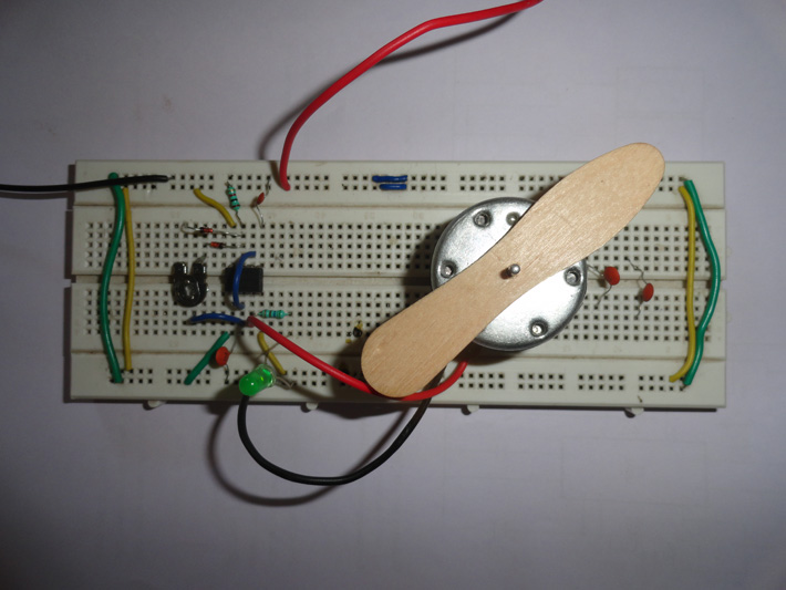
It is a simple circuit with the help of which you can control the speed of DC motor. You can also use it control the speed of windscreen wipers used in automobiles or it can be used in toys. Easy to install because of less components used and works well on wide range of power supply from 5V to 12V.
This circuit to control speed of dc motor is based on single IC that is NE555 which work as a-stable multi-vibrator. In this mode 555 timer is not stable and its output is continuously changes from low to high or from high to low. This continuous change from one state to another (high to low and then back to original state) produces a continuous square wave output. Now if the power supply is first connected to a-stable circuit then initially the timing capacitor C1 is discharged. The voltage at pin2 is 0V and the output of timer is driven HIGH. Now C1 starts charging through VR1 and R2. Capacitor C1 is also connected to pin6 which is threshold input of the timer.When the voltage through C1 goes below 1/3 of the power supply, the output of the lower comparator reaches a new value. This doesn’t change the logic state of the flip flop which means that the output remain low. The second comparator’s input get the voltage from pin 6 which is threshold input and 2/3 Vcc from internal voltage divider. When the voltage through C1 goes below 2/3 of the power supply the output of the second comparator reaches a new level. The flip-flop changes their state and the output becomes HIGH. So the output of 555 timer goes from HIGH to LOW.

Circuit Diagrams
Project Video
Filed Under: Electronic Projects
Filed Under: Electronic Projects


Questions related to this article?
👉Ask and discuss on Electro-Tech-Online.com and EDAboard.com forums.
Tell Us What You Think!!
You must be logged in to post a comment.