There are many applications that require setting the angular position of load/object.
For example,
- It is required to set the precise angular position of the rudder, aileron, and elevator to fly aircraft
- In a ship, setting the angular position of the rudder will set the direction of navigation
- In a CCTV surveillance system, it may be required to set camera angle to get a proper and exact view
- In a howitzer gun, it is required to set the angular position of the nozzle so that it will hit the target
Thus, there are so many such examples where we have to set the proper angular position of any object like a rudder, camera, gun nozzle, dish antenna, light/sound beam source, etc.
In all such system, we have to build either an open-loop or closed-loop control system in which there is a control input (mostly by a human) that is given to the system that further controls any actuator which actually sets the angular position of the object using some mechanism. The figure given below shows a block diagram of an open-loop control system.

The project given here is one such type of open-loop control system. It uses a rotary encoder as an input and a stepper motor as an actuator. Let us see the system block diagram first and then I will discuss how to build this system
System Block Diagram
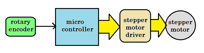
Rotary encoder – it generates pulses as its shaft is rotated. It gives these pulses as input to the microcontroller.

Microcontroller – it takes pulse output from the encoder – calculates angular rotation of its shaft – rotates the stepper motor to the required angular position.
Stepper motor driver – it provides the required current to the motor and drives the motor.
Stepper motor – it is used to set the angular position of any object attached to it with any mechanism.
Now let us see how to build this system. We’ll start by collecting the required items.
List of required items
- Rotary encoder module
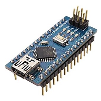
- Arduino NANO board
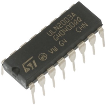
- ULN2003A chip
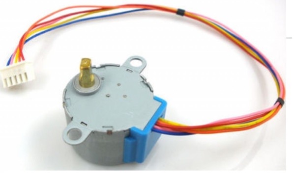
- Unipolar type 5V stepper motor
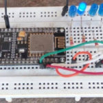
The circuit is very easy to build because it requires only three components. It can be easily built using breadboard and jumper wires. Here is the snap of the circuit built on the Arduino nano development board.
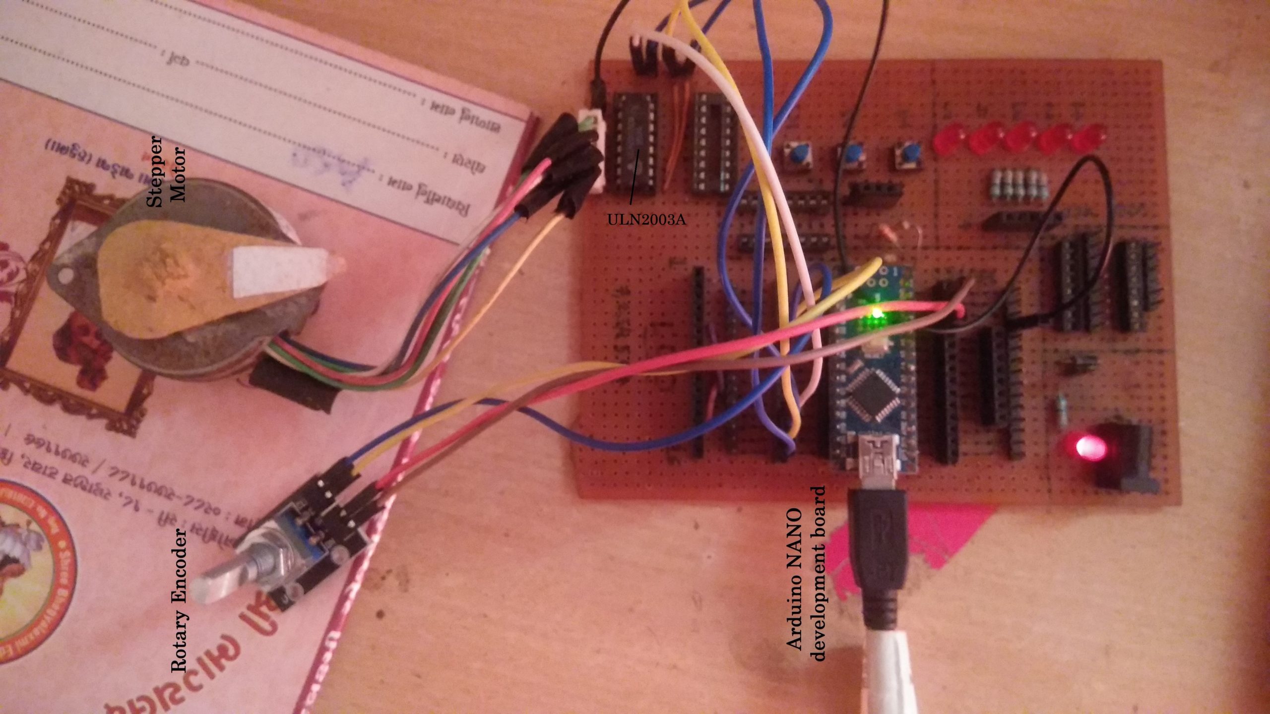
Circuit diagram
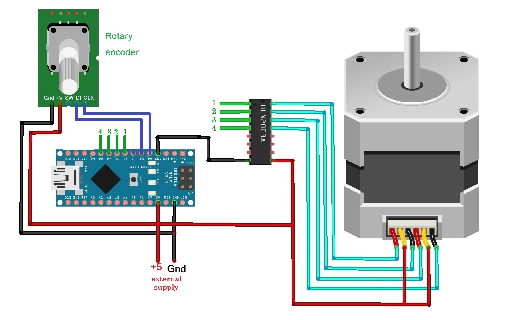
As shown in the figure the circuit is built using only three components 1) rotary encoder module 2) Arduino NANO development board and 3) motor driver chip ULN2003A
- The rotary encoder module has 5 interfacing pins. Out of these 5 pins – 2 pins are for Vcc and Gnd and they are connected with 5 V output and Gnd of Arduino board
- Its other 2 pins DI and CLK are connected with Arduino board digital pins D2 and D3 respectively. Its SW pin is not used in this project
- Arduino board pins D5 – D8 are used to drive the stepper motor using the ULN2003A chip. These pins are connected with input pins IN1 – IN4 as shown and chip output pins OUT1 – OUT4 are connected with the stepper motor
- The common terminal of the stepper motor is connected to an external 5 V supply
- Arduino board, rotary encoder module, and ULN2003 chip all are also given the same 5 V supply
Circuit working and operation
The circuit working is very simple.
In one sentence I can say, as the rotary encoder is rotated clockwise or anticlockwise at a specific angular position – the stepper motor also rotates and moves to the required angular position.
The angular position of the encoder in either direction (CW or CCW) is mapped with the angular position of the motor in the same direction.
This means if the encoder is rotated in 90o CW direction – the stepper motor also rotates 90o CW. And similarly, if the encoder is rotated 60o CCW direction – the stepper motor rotates at 60o CCW.
The stepper motor used here has a step angle of 7.5o per pulse. So this motor can rotate minimum at a 30o angle.
The rotary encoder generates 12 pulses / 1 rotation. That means it generates pulse at every (1 rotation) = 360o / 12 = 30o rotation.
Thus we can directly map encoder rotation of 30o (1 pulse) into 30o rotation of stepper motor.
To understand the circuit operation in more detail first we have to go through the working of the rotary encoder.
Working of the rotary encoder
The rotary encoder consists of a slotted disk connected to common ground pin C and two contact pins A and B as shown in the figure below.
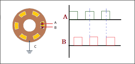
When you turn the knob, A and B come in contact with the common ground pin C, in a particular order according to the direction in which you are turning the knob.
When they come in contact with the common ground they produce signals. These signals are shifted 90° out of phase with each other as one pin comes in contact with the other pin. This is called quadrature encoding.
When you turn the knob clockwise, the A pin connects first, followed by the B pin. When you turn the knob counterclockwise, the B pin connects first, followed by the A pin.
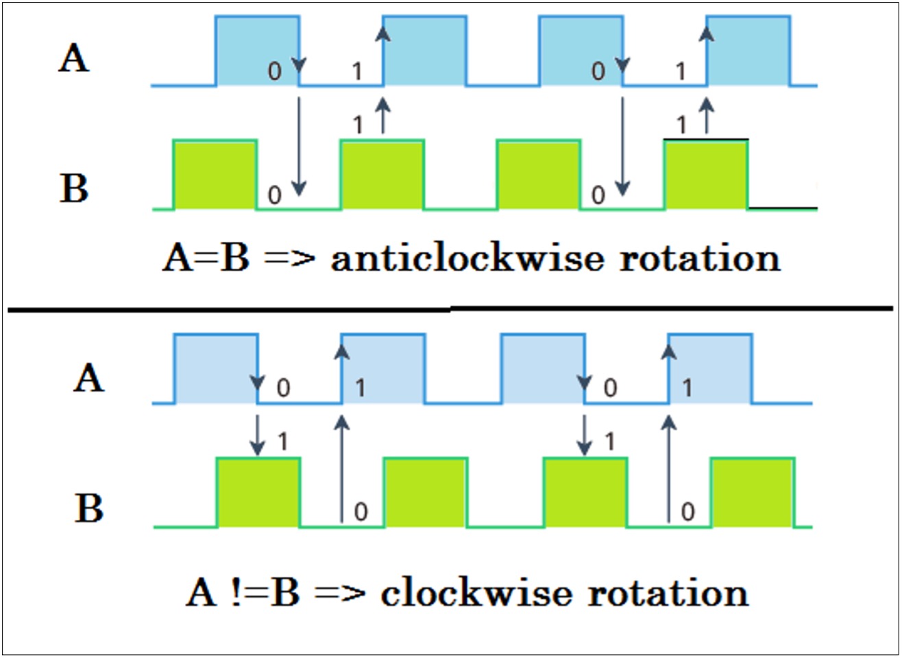
By tracking when each pin connects to and disconnects from the ground, we can use these signal changes to determine in which direction the knob is being rotated. You can do this by simply observing the state of B when A changes state.
When the A changes state:
- if B and A are not equal, then the knob was turned clockwise
- if B and A are equal, then the knob was turned counterclockwise
See the figure given below
So these A and B outputs are DI and CLK pins of the rotary encoder module. The Arduino checks pulse output from both and determines encoder is rotated clockwise or anti-clockwise. Arduino counts pulses and with each pulse count in CW or CCW direction, it rotates the motor to 30o in the same direction
The complete working and operation of the circuit is based on the program downloaded into the internal FLASH memory of Arduino microcontroller ATMega328. The program is written in C language using Arduino IDE. The program uses the Uni_polar_Stepper library to control and rotate the unipolar type stepper motor used here. Please go through Uni_polar_Stepper library documentation for more details. Here is the program code:
You may also like:


Filed Under: Electronic Projects

Questions related to this article?
👉Ask and discuss on Electro-Tech-Online.com and EDAboard.com forums.
Tell Us What You Think!!
You must be logged in to post a comment.