Engineers Garage

  • Electronic Projects & Tutorials
    • Electronic Projects
      • Arduino Projects
      • AVR
      • Raspberry pi
      • ESP8266
      • BeagleBone
      • 8051 Microcontroller
      • ARM
      • PIC Microcontroller
      • STM32
    • Tutorials
      • Audio Electronics
      • Battery Management
      • Brainwave
      • Electric Vehicles
      • EMI/EMC/RFI
      • Hardware Filters
      • IoT tutorials
      • Power Tutorials
      • Python
      • Sensors
      • USB
      • VHDL
    • Circuit Design
    • Project Videos
    • Components
  • Articles
    • Tech Articles
    • Insight
    • Invention Stories
    • How to
    • What Is
  • News
    • Electronic Product News
    • Business News
    • Company/Start-up News
    • DIY Reviews
    • Guest Post
  • Forums
    • EDABoard.com
    • Electro-Tech-Online
    • EG Forum Archive
  • DigiKey Store
    • Cables, Wires
    • Connectors, Interconnect
    • Discrete
    • Electromechanical
    • Embedded Computers
    • Enclosures, Hardware, Office
    • Integrated Circuits (ICs)
    • Isolators
    • LED/Optoelectronics
    • Passive
    • Power, Circuit Protection
    • Programmers
    • RF, Wireless
    • Semiconductors
    • Sensors, Transducers
    • Test Products
    • Tools
  • Learn
    • eBooks/Tech Tips
    • Design Guides
    • Learning Center
    • Tech Toolboxes
    • Webinars & Digital Events
  • Resources
    • Digital Issues
    • EE Training Days
    • LEAP Awards
    • Podcasts
    • Webinars / Digital Events
    • White Papers
    • Engineering Diversity & Inclusion
    • DesignFast
  • Guest Post Guidelines
  • Advertise
  • Subscribe

Stepper Motor : Basics, Types and Working

By Nikhil Agnihotri February 18, 2011

 
What is a stepper motor?
A Stepper Motor or a step motor is a brushless, synchronous motor which divides a full rotation into a number of steps. Unlike a brushless DC motor which rotates continuously when a fixed DC voltage is applied to it, a step motor rotates in discrete step angles. The Stepper Motors therefore are manufactured with steps per revolution of 12, 24, 72, 144, 180, and 200, resulting in stepping angles of 30, 15, 5, 2.5, 2, and 1.8 degrees per step. The stepper motor can be controlled with or without feedback.
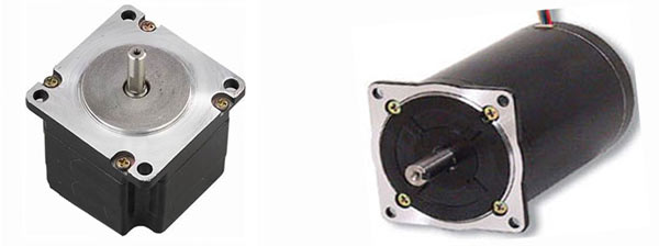
An image of commonly used brushless DC stepper motor


Fig. 1: An Image Of Commonly Used Brushless DC Stepper Motor

 
How a stepper motor works?
Stepper motors work on the principle of electromagnetism. There is a soft iron or magnetic rotor shaft surrounded by the electromagnetic stators. The rotor and stator have poles which may be teethed or not depending upon the type of stepper. When the stators are energized the rotor moves to align itself along with the stator (in case of a permanent magnet type stepper) or moves to have a minimum gap with the stator (in case of a variable reluctance stepper). This way the stators are energized in a sequence to rotate the stepper motor. Get more information about working of stepper motors through interesting images at the stepper motor Insight.
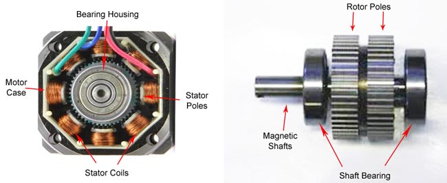
 
General Overview of Internal structure and Working of typical Stepper Motor
 
Fig. 2: General Overview Of Internal Structure And Working Of Typical Stepper Motor
 
Types of Stepper Motor
By construction the step motors come into three broad classes:
1.      Permanent Magnet Stepper
2.      Variable Reluctance Stepper
3.      Hybrid Step Motor
These three types have been explained in detail in the following sections.


Type1: Permanent Magnet

1.    Permanent Magnet Stepper :
The rotor and stator poles of a permanent magnet stepper are not teethed. Instead the rotor have alternative north and south poles parallel to the axis of the rotor shaft.
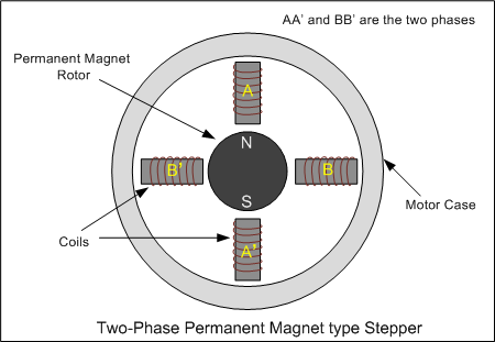
Crossectional Diagram of Two phase permanent stepper Motor
 
Fig. 3: Crossectional Diagram Of Two Phase Permanent Stepper Motor
 
When a stator is energized, it develops electromagnetic poles. The magnetic rotor aligns along the magnetic field of the stator. The other stator is then energized in the sequence so that the rotor moves and aligns itself to the new magnetic field. This way energizing the stators in a fixed sequence rotates the stepper motor by fixed angles.
 
Diagram explaining working of Permanent Magnet Stepper Motor
 
Fig. 4: Diagram Explaining Working Of Permanent Magnet Stepper Motor
 
The resolution of a permanent magnet stepper can be increased by increasing number of poles in the rotor or increasing the number of phases.
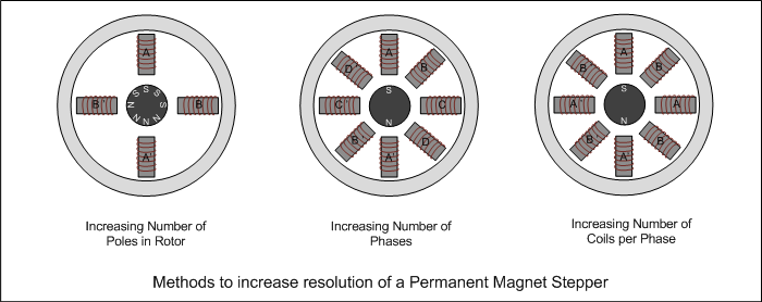
Figure showing diffrent methods to increase resolution of Permanent Magnet Stepper Motor
 
Fig. 5: Figure Showing Ways To Increase Resolution Of Permanent Magnet Stepper Motor


Type2: Variable Reluctance

2.    Variable reluctance stepper :   
The variable reluctance stepper has a toothed non-magnetic soft iron rotor. When the stator coil is energized the rotor moves to have a minimum gap between the stator and its teeth.
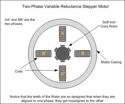
Basic Diagram of Two -phase variable reluctance stepper motor
 
Fig. 6: Basic Diagram Of Two-Phase Variable Reluctance Stepper Motor
 
The teeth of the rotor are designed so that when they are aligned with one stator they get misaligned with the next stator. Now when the next stator is energized, the rotor moves to align its teeth with the next stator. This way energizing stators in a fixed sequence completes the rotation of the step motor.
 
Diagram explaining working of Variable Reluctance Stepper
 
Fig. 7: Diagram Explaining Working Of Variable Reluctance Stepper
 
The resolution of a variable reluctance stepper can be increased by increasing the number of teeth in the rotor and by increasing the number of phases.
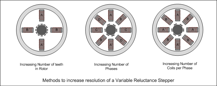
 
Figure showing diffrent methods to increase resolution of Variable reluctance Stepper Motor
 
Fig. 8: Figure Showing Ways To Increase Resolution Of Variable Reluctance Stepper Motor


Type3: Hybrid

3.    Hybrid stepper :
A hybrid stepper is a combination of both permanent magnet and the variable reluctance. It has a magnetic teethed rotor which better guides magnetic flux to preferred location in the air gap.
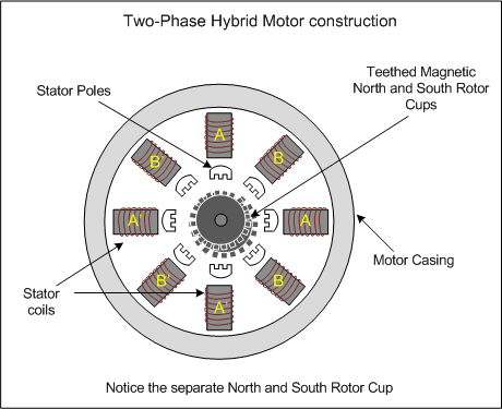
Construction of Two phase hybrid Motor
 
Fig. 9: Construction Of Two phase Hybrid Motor
 
The magnetic rotor has two cups. One for north poles and second for the south poles. The rotor cups are designed so that that the north and south poles arrange in alternative manner. Check out the insight of a Hybrid Stepper Motor.
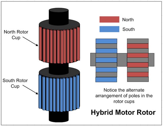
Diagram showing Internal structure of Magnetic Rotor in Hybrid Motor
 
Fig. 10: Diagram Showing Internal Structure Of Magnetic Rotor In Hybrid Motor
 
The Hybrid motor rotates on same principle of energizing the stator coils in a sequence.
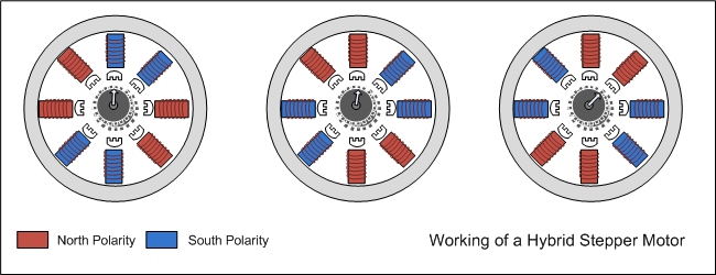
 
Diagram explaining working of Hybrid Stepper Motor
 
Fig. 11: Diagram Explaining Working Of Hybrid Stepper Motor


Types of Wiring

Types of Winding and Lead-out
The step motors are mostly two phase motors. These can be unipolar or bipolar. In unipolar step motor there are two winding per phase. The two winding to a pole may have one lead common i.e. centre tapped. The unipolar motor so, have five, six or eight leads. In the designs where the common of two poles are separate but centre tapped, motor have six leads. If the centre taps of the two poles are internally short, the motor has five leads. Eight lead unipolar facilitates both series and parallel connection whereas five lead and six lead motors have series connection of stator coils. The unipolar motor simplifies the operation because in operating them there is no need to reverse the current in the driving circuit. These are also called bifilar motors.
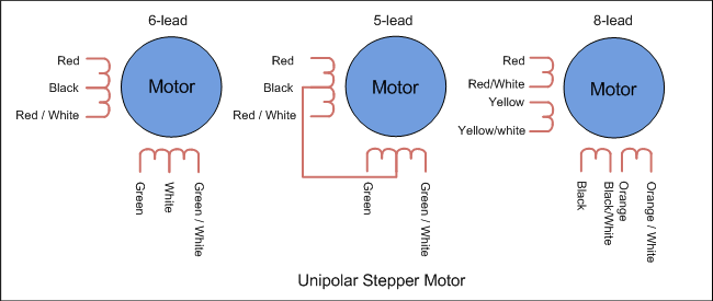
 
Wiring Diagram of Unipolar stepper motor with diffrent leads
 
Fig. 12: Wiring Diagram Of Unipolar Stepper Motor With Diffrent Leads
 
In bipolar stepper there is single winding per pole. The direction of current need to be changed by the driving circuit so the driving circuit of the bipolar stepper becomes complex. These are also called unifilar motors.
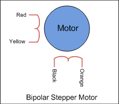
Wiring Diagram of Bipolar stepper motor with lead outs
 
Fig. 13: Wiring Diagram Of Bipolar Stepper Motor With Lead Outs


Stepping Modes

There are three stepping modes of a stepper motor. The stepping mode refers to the pattern of sequence in which stator coils are energized.
1.      Wave drive (One phase ON at a time)
2.      Full drive (Two phase ON at a time)
3.      Half drive (One and two phase ON at a time)
 
1.    Wave drive :
In wave drive stepping mode only one phase is energized at a time.
Wiring Diagram of Bipolar stepper motor with lead outs
 
Fig. 14: Wave Drive Stepping Mode Pattern In Stepper Motor
2.    Full Drive :
In full drive, two phases are energized at a time.
Wiring Diagram of Bipolar stepper motor with lead outs
 
Fig. 15:Full Drive Stepping Mode pattern In Stepper Motor
 
3.    Half Drive :

In half drive, alternately one and two phases are energized. This increases the resolution of the motor.

Wiring Diagram of Bipolar stepper motor with lead outs

Fig. 16: Half Drive Stepping Mode Pattern In Stepper Motor


Filed Under: Articles
Tagged With: hybrid, motor, permanent magnet, stepper motor, variable reluctance
 

Next Article

← Previous Article
Next Article →

Questions related to this article?
👉Ask and discuss on Electro-Tech-Online.com and EDAboard.com forums.


Tell Us What You Think!! Cancel reply

You must be logged in to post a comment.

EE TECH TOOLBOX

“ee
Tech Toolbox: 5G Technology
This Tech Toolbox covers the basics of 5G technology plus a story about how engineers designed and built a prototype DSL router mostly from old cellphone parts. Download this first 5G/wired/wireless communications Tech Toolbox to learn more!

EE Learning Center

EE Learning Center
“engineers
EXPAND YOUR KNOWLEDGE AND STAY CONNECTED
Get the latest info on technologies, tools and strategies for EE professionals.

HAVE A QUESTION?

Have a technical question about an article or other engineering questions? Check out our engineering forums EDABoard.com and Electro-Tech-Online.com where you can get those questions asked and answered by your peers!


RSS EDABOARD.com Discussions

  • BF999 Input and output impedance
  • Control for DC motor
  • Industrial Relay Board Design for Motorcycle Use
  • Sendust vs Ferrite for SMPS
  • On/Off Slide Switch Reassembly Help

RSS Electro-Tech-Online.com Discussions

  • Wierd makita battery
  • More fun with ws2812 this time XC8 and CLC
  • I Wanna build a robot
  • using a RTC in SF basic
  • Is AI making embedded software developers more productive?

Featured – LoRa/LoRaWan Series

  • What is the LoRaWAN network and how does it work?
  • Understanding LoRa architecture: nodes, gateways, and servers
  • Revolutionizing RF: LoRa applications and advantages
  • How to build a LoRa gateway using Raspberry Pi
  • How LoRa enables long-range communication
  • How communication works between two LoRa end-node devices

Recent Articles

  • STMicroelectronics unveils SoC based on secure MCU
  • Nexperia’s 48 V ESD diodes support higher data rates with ultra-low capacitance design
  • Taoglas releases Patriot antenna with 18 integrated elements covering 600 to 6000 MHz
  • Amphenol RF introduces SMPM to SMPM assemblies on RG-178 cable
  • Infineon launches 3D magnetic sensors with ±50 mT to ±160 mT measurement ranges

EE ENGINEERING TRAINING DAYS

engineering

Submit a Guest Post

submit a guest post
Engineers Garage
  • Analog IC TIps
  • Connector Tips
  • Battery Power Tips
  • DesignFast
  • EDABoard Forums
  • EE World Online
  • Electro-Tech-Online Forums
  • EV Engineering
  • Microcontroller Tips
  • Power Electronic Tips
  • Sensor Tips
  • Test and Measurement Tips
  • 5G Technology World
  • Subscribe to our newsletter
  • About Us
  • Contact Us
  • Advertise

Copyright © 2025 WTWH Media LLC. All Rights Reserved. The material on this site may not be reproduced, distributed, transmitted, cached or otherwise used, except with the prior written permission of WTWH Media
Privacy Policy

Search Engineers Garage

  • Electronic Projects & Tutorials
    • Electronic Projects
      • Arduino Projects
      • AVR
      • Raspberry pi
      • ESP8266
      • BeagleBone
      • 8051 Microcontroller
      • ARM
      • PIC Microcontroller
      • STM32
    • Tutorials
      • Audio Electronics
      • Battery Management
      • Brainwave
      • Electric Vehicles
      • EMI/EMC/RFI
      • Hardware Filters
      • IoT tutorials
      • Power Tutorials
      • Python
      • Sensors
      • USB
      • VHDL
    • Circuit Design
    • Project Videos
    • Components
  • Articles
    • Tech Articles
    • Insight
    • Invention Stories
    • How to
    • What Is
  • News
    • Electronic Product News
    • Business News
    • Company/Start-up News
    • DIY Reviews
    • Guest Post
  • Forums
    • EDABoard.com
    • Electro-Tech-Online
    • EG Forum Archive
  • DigiKey Store
    • Cables, Wires
    • Connectors, Interconnect
    • Discrete
    • Electromechanical
    • Embedded Computers
    • Enclosures, Hardware, Office
    • Integrated Circuits (ICs)
    • Isolators
    • LED/Optoelectronics
    • Passive
    • Power, Circuit Protection
    • Programmers
    • RF, Wireless
    • Semiconductors
    • Sensors, Transducers
    • Test Products
    • Tools
  • Learn
    • eBooks/Tech Tips
    • Design Guides
    • Learning Center
    • Tech Toolboxes
    • Webinars & Digital Events
  • Resources
    • Digital Issues
    • EE Training Days
    • LEAP Awards
    • Podcasts
    • Webinars / Digital Events
    • White Papers
    • Engineering Diversity & Inclusion
    • DesignFast
  • Guest Post Guidelines
  • Advertise
  • Subscribe