This tutorial is about generating pwm (pulse width modulation) signal with stm32f103 microcontroller using its internal hardware timers. Stm32f103 microcontroller components/peripherals initialization code is generated using stmcubemx ide and code is written and compiled in keil MDK-ARMv6 ide. A simple led is derived on a fixed pwm signal output. Led dims and blinks according to the duty cycle and frequency that a particular pwm pin is outputting. A single Pwm signal is generated/Outputted in the tutorial, but you can generate multiple pwm signals with the same method and settings.
I am going to output a 1 Hz frequency and 50% duty cycle pwm(pulse width modulation) signal using timer-4 of stm32f103 microcontroller. Timer-4 channel-1 is used to output signal. Channel-1 corresponds to PB6 pin of stm32f103 microcontroller. At PB6 an led is connected on which pwm output can be seen. 1 Hz frequency in time domain is T=1/f > T=1/1 Hz > T=1 s. So 1 Hz frequency translates to 1 s and my duty cycle is 50% so the led at PB6 pin will blink at half a second rate.
How to Generate Desired/Specific PWM Frequency? Formula derivation and Calculations.
Timer Tick FrequencyTimer tick frequency is the frequency at which the timer is completing its one instruction cycle.
Counter FrequencyCounter Frequency is the frequency at which we want our timer tick counter to increment.
|
Stm32f103 Pwm(Pulse Width Modulation) frequency calculation formula
|
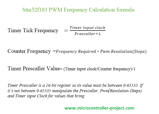
Pwm Resolution
|
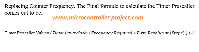
Stm32f103 pwm formula for Prescaller value
|
Replacing the Counter Frequency with its formula in the Timer Prescaller Value equations yields the equation given on the left side. Now its easy to determine the prescaller value.
|
Stmcube-Mx code initializing steps an generating keil MDK-ARM code
I assume that you people are familiar with stmcube mx project creating process and know about the necessary steps. If not then take a simple tutorial

Timer 3 and 4 are stand alone and they do not collide with any other peripheral function. So its good to use them. I am using Timer 4 in the project/tutorial.
I am using Internal clock source so check this check box in the timer settings. I am using timer 4, channel 1 for pwm output so i selected channel 1. Channel 1 corresponds to PB6 of stm32f103 microcontroller. The settings diagram is given on the right side.
Calculating Values for 1Hz frequency and 50% duty cycle pwm signal output
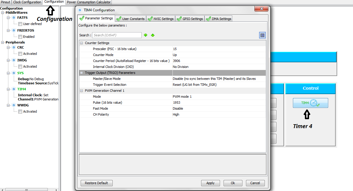
In the final timer settings it’s time to input the Counter Period/Pwm Resolution(Steps), Prescaler value and Pulse required. Pulse is the duty cycle required and in our case its 50%. Lets Solve the upper formula according to the pwm calculation formula’s given above.
Given values:
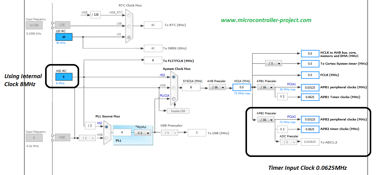
Timer Input Clock = 0.0625Mhz or 62500Hz
Required Frequency = 1 Hz (In Time Domain 1 second)
Counter Period/Pwm Resolution(Steps) = 3906 (I picked a random value)
Counter Frequency= frequency required * Counter Period
Counter Frequency= 1Hz * 3906 =3906 Hz
Timer Prescaller value=( Timer Input Clock/Counter Frequency)-1
Timer Prescaller value=(62500 Hz / 3906 Hz) – 1 = 15
Now we have both the value’s Timer Presaller value, Counter Period/Pwm Resolution(Steps) and also they are in 16-bit range. Now input the values in the timer 4 configuration. I selected the counter to be in UP mode(Count for 0 to 3906). Pulse is the duty cycle in our case its 50% so 3906*50% > 3906*0.5 = 1953.
Watch the Project Video Here…
You may also like:


Filed Under: Electronic Projects, STM32, STM32.

Questions related to this article?
👉Ask and discuss on Electro-Tech-Online.com and EDAboard.com forums.
Tell Us What You Think!!
You must be logged in to post a comment.