This is an advance tutorial on pwm generation. We are going to output/generate a variable pwm signal with stm32f103 microcontroller. Variable pwm signal is used for controlling the speed of Dc motors and fans. It is also used in dimmers to dim and bright the light bulbs, led arrays etc. Pwm solar chargers also work on variable pwm signal. Servo motors angle and direction is also controlled with pwm signal. In the previous tutorial we learned how to generate pwm(pulse width modulated) signal using internal timers of stm32f103 microcontroller. We also derived the formula for calculating different values required to generate a particular/specific frequency pwm signal. Pwm configuration required to be done in stm32cubemx code generator is also step by step done and discussed in the tutorial. This tutorial is based on the code and configuration done in the previous one. So i recommend you to first see the previous tutorial than start with it. You can easily understand the code below once you take the previous tutorial. Visit the link below.
Now you have taken the above tutorial lets start this tutorial. I am going to generate variable pwm signal on 1 Hz frequency that is generated in the previous tutorial. 1 Hz in time domain is equal to 1 second. I am going to output this variable signal on a led which is connected to output of stm32f103. Timer-4 channel-1 of stm32f103 is used to output variable pwm signal. Channel-1 corresponds to Prt-B Pin number 6 – PB-6 pin of stm32f103 microcontroller.
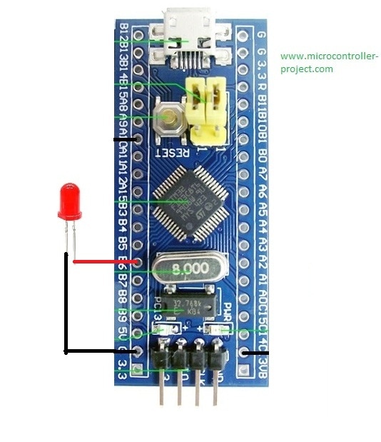
Stm32f103 variable pwm output
|
I am using this cheap $1.5 stm32f103c8t6 development board purchased from aliexpress. It does not have a programmer built on it. I am using an external stlink v2 programmer to program the module.
Circuit Diagram Circuit of the project is simple connect the anode(positive led) of led to pin PB-6 and ground the cathode(negative leg). No resistor is required since the stm32 works on 3.3 v and its gpio’s also source max 3.3 volt which is near the voltage required by a red color led. |
I am going to increment the duty cycle of output signal from 0 to 100% and then back from 100% to 0. You can see the effect on the led in the video at the bottom of the post
The code of the project is simple i just added the functionality of duty cycle increment and decreas. For 1 Hz frequency we calculated the counter value which is 3906(Previous tutorial). 3906 is the max 100% duty cycle. I am going to increment duty cycle from 0 to 3906(0-100%). After increment i will decrease it in descending order from 3906 to 0(100%-0). This function is achieved by placing the duty cycle in for loop. For increment phase for loop runs from 0 to 3906 and for decreasing it rolls back from 3906 to 0. The important statement in the whole code is.
__HAL_TIM_SetCompare(&htim4, TIM_CHANNEL_1, pwm);
This macro/statement is setting/updating the pwm period. It updates the capture compare register which is continuously capturing and comparing the timer count value with our pwm period value.
In the video the led blinks its because i am working on high frequency 1 Hz. Which in time domain is equal to 1 s. Now varying the duty cycle, if increasing the duty cycle the led blinks at higher rate, if decreasing the duty cycle the led blinks at slower rate. In many examples about the variable pwm it is shown that the led fads in and out upon variation in pwm duty cycle. In those examples the frequency of the pin is 10 ms to 100 ms and at those frequencies their is no blink possible. If you want the led to fan in and out just change the channel frequency.
Download the project code/files and please give us your feed back on the project. In case if you have any queries please write them below in the comments section.
Watch the Project Video Here…
Filed Under: Microcontroller Projects, STM32.

Questions related to this article?
👉Ask and discuss on Electro-Tech-Online.com and EDAboard.com forums.
Tell Us What You Think!!
You must be logged in to post a comment.