Engineers Garage

  • Projects and Tutorials
    • Electronic Projects
      • 8051
      • Arduino
      • ARM
      • AVR
      • PIC
      • Raspberry pi
      • STM32
    • Tutorials
    • Circuit Design
    • Project Videos
    • Components
  • Articles
    • Tech Articles
    • Insight
    • Invention Stories
    • How to
    • What Is
  • News
    • Electronic Products News
    • DIY Reviews
    • Guest Post
  • Forums
    • EDABoard.com
    • Electro-Tech-Online
    • EG Forum Archive
  • Digi-Key Store
    • Cables, Wires
    • Connectors, Interconnect
    • Discrete
    • Electromechanical
    • Embedded Computers
    • Enclosures, Hardware, Office
    • Integrated Circuits (ICs)
    • Isolators
    • LED/Optoelectronics
    • Passive
    • Power, Circuit Protection
    • Programmers
    • RF, Wireless
    • Semiconductors
    • Sensors, Transducers
    • Test Products
    • Tools
  • EE Resources
    • DesignFast
    • LEAP Awards
    • Oscilloscope Product Finder
    • White Papers
    • Webinars
  • EE Learning Center
  • Women in Engineering

Stopwatch using 8051 microcontroller (AT89C51)

By Himanshu Choudhary

A stopwatch is a timepiece that measures the amount of time between any two occurrences. Usually, at the first occurrence, the stopwatch is started while at the second it is stopped. To use it again, a reset option is also provided with the stopwatch. The total time elapsed can thus be obtained. A stopwatch is very commonly used in racing competitions and other gaming activities. The circuit given here is a digital stopwatch that displays time on four seven segment displays using 8051 microcontroller (AT89C51) .


The stopwatch keeps the track of time the same way as a simple digital clock does. It is basically an up time counter that starts from 00:00. The control options are provided by means of tactile switches which are active low. This circuit uses three such switches for following operations:
Switch 1 (S1)   :           Start               
Switch 2 (S2)   :           Stop                
Switch 3 (S3)   :           Reset              
 
Initially when Vcc supply is provided to the circuit, the stopwatch goes in reset mode with 00:00 display state on seven segments. The stopwatch starts running when S1 is pressed. The time is displayed on four seven segments (in common anode configuration) by using the concept of multiplexing. (Also refer Digital Clock) On pressing S2, the stopwatch stops and displays the total time elapsed since the start. It can be taken to reset mode at any instant by using S3.
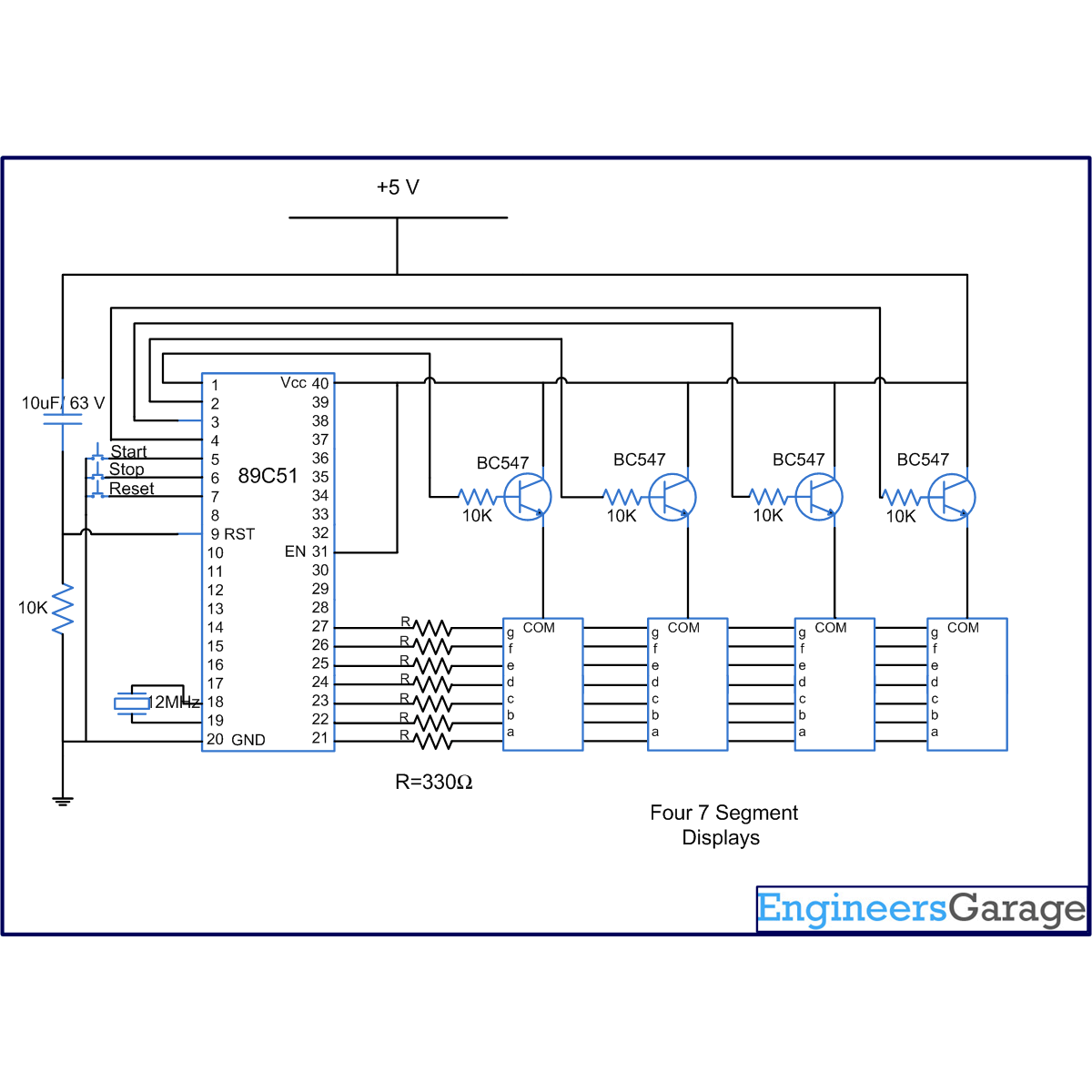
The seven segments are interfaced to port P2 of the microcontroller AT89C51 through its data pins (a – h). The enable pins are connected to pins 1-4 of port P1 (P1^0 – P1^3). The switches S1-S3 are connected to pins 5-7 of port P1 (P1^4 – P1^6).


Project Source Code

###

//Program to make a stopwatch

#include<reg51.h>
#define msec 1
unsigned int sec1,sec2;
int sec1_1,sec1_2,sec2_1,sec2_2;

unsigned int digi_val[10]={0x40,0xF9,0x24,0x30,0x19,0x12,0x02,0xF8,0x00,0x10};
sbit dig_ctrl_1=P1^0;  // Declare the control pins of seven segments
sbit dig_ctrl_2=P1^1;
sbit dig_ctrl_3=P1^2;
sbit dig_ctrl_4=P1^3;
sbit start_pin = P1^4;  // Start pin to start the watch.
sbit stop_pin = P1^5;  // Stop pin to stop the watch.
sbit reset_pin = P1^6;  // Reset pin to reset the watch.
int s,t;

void mplex_delay(unsigned int time)  // Function to provide a time delay of approximatelty one second using Timer 1
{
int i,j;
for (i=0;i<=time;i++)
  for(j=0;j<=50;j++);
}

void digi_out(unsigned int current_num)
{
    P2=digi_val[current_num];
     mplex_delay(msec);
}

void display(unsigned int dig1,unsigned int dig2)  // Function to display the digits on seven segmnet. For more details refer seven segment multiplexing.
{
    sec1_2=dig1%10;
sec1_1=dig1/10;
sec2_2=dig2%10;
sec2_1=dig2/10;
TMOD=0x01;  //Enable Timer 0
TL0=0xFF;
TH0=0xDB;
TR0=1;  // Triger Timer 0
while(TF0==0)
{
  dig_ctrl_1 = 1;
  dig_ctrl_2 = dig_ctrl_3 = dig_ctrl_4 = 0;
  digi_out(sec1_1);
  dig_ctrl_2 = 1;
  dig_ctrl_1 = dig_ctrl_3 = dig_ctrl_4 = 0;
  digi_out(sec1_2);
  dig_ctrl_3 = 1;
  dig_ctrl_2 = dig_ctrl_1 = dig_ctrl_4 = 0;
  digi_out(sec2_1);
  dig_ctrl_4 = 1;
  dig_ctrl_2 = dig_ctrl_3 = dig_ctrl_1 = 0;
  digi_out(sec2_2);
}

TR0=0;
TF0=0;
}

void main()
{
while(1)
{
start:  // Segment to start the stop watch
  start_pin = 1;
  stop_pin = 1;
  reset_pin = 1; 
  dig_ctrl_1 = 0;
  dig_ctrl_2 = 0;
  dig_ctrl_3 = 0;
  dig_ctrl_4 = 0;
  P2 = 0xFF;
  s = t = 0;
  while(start_pin == 1)// Check if start pin is pressed
  {
  display(0,0);
  }

stopwatch:  // Segment to stop the watch
  for (sec1=s;sec1<=99;sec1++)
  {
   if (stop_pin == 0 )  //Check if stop pin is pressed
   break;
    for (sec2=t;sec2<=99; sec2++)
    {
    if (stop_pin == 0 )  //Check if stop pin is pressed
    break;
    t=0;
    display(sec1,sec2);
    }
  }
  stop_pin = 1;
  s = sec1;
  t = sec2;
 
  while ( start_pin != 0 && reset_pin != 0 )  //Check if start pin or reset pins are not pressed
  {
  display(sec1,sec2);
  }
 
  if (start_pin == 0)  //Check if start pin is pressed
  {
  goto stopwatch;
  }
  else
  {
   if (reset_pin == 0 )  //Check if reset pin is pressed
   {
   s = t = 0;
   goto start;
   }
  }
}
}

###


Circuit Diagrams

Circuit-Diagram-of-Stopwatch-using-8051-microcontroller-AT89C51

Project Components

  • AT89C51 Microcontroller
  • Piezo Buzzer
  • Seven Segment Display
  • Transistor BC547

Project Video


Filed Under: 8051 Microcontroller
Tagged With: 8051, clock, microcontroller, stopwatch
 

Questions related to this article?
👉Ask and discuss on EDAboard.com and Electro-Tech-Online.com forums.


Tell Us What You Think!! Cancel reply

You must be logged in to post a comment.

HAVE A QUESTION?

Have a technical question about an article or other engineering questions? Check out our engineering forums EDABoard.com and Electro-Tech-Online.com where you can get those questions asked and answered by your peers!


Featured Tutorials

  • Designing Gate Driver Circuit and Switching Mechanism for Modified Sine Wave Inverter – (Part 9/17)
  • Completing Modified Sine Wave Inverter Design with Full Bridge Circuit and Step Up Transformer – (Part 10/17)
  • Designing an Offline UPS – Part (12 /17)
  • How to reduce Switching Time of a Relay – (Part 15/17)
  • Testing MOSFET – (Part 16/17)
  • Driving High Side MOSFET using Bootstrap Circuitry – (Part 17/17)

Stay Up To Date

Newsletter Signup

Sign up and receive our weekly newsletter for latest Tech articles, Electronics Projects, Tutorial series and other insightful tech content.

EE Training Center Classrooms

EE Classrooms

Recent Articles

  • New automotive radar sensor enables reliable in-cabin monitoring system
  • TI breaks ground on 300-mm semiconductor wafer-fabrication plants in Texas
  • New wireless AR Smart Viewer reference design
  • Infineon launches scalable and wireless charging platform with configurable controllers
  • First single-core MPU with MIPI CSI-2 camera interface and audio

Most Popular

5G 555 timer circuit 8051 ai Arduino atmega16 automotive avr dc motor display Electronic Part Electronic Parts Fujitsu ic infineontechnologies integratedcircuit Intel IoT ir lcd ldr led maximintegratedproducts microchip microchiptechnology Microchip Technology microcontroller microcontrollers mosfet motor powermanagement Raspberry Pi remote renesaselectronics renesaselectronicscorporation Research samsung semiconductor sensor software STMicroelectronics switch Technology vishayintertechnology wireless

RSS EDABOARD.com Discussions

  • A circuit that can adjust a resistance and probing a voltage node
  • DC to DC buck converter
  • A circuit that can probe 2 currents and adjust the resistor
  • Microsoft Project 2019 dependencies
  • MOSFET ORing circuit simulation (LTspice)

RSS Electro-Tech-Online.com Discussions

  • Enclosure sought
  • Need help using a common power supply for two devices
  • Fletcher's Law
  • Setting the 18F24K20 to digital.
  • Multistage BJT amplifier
Engineers Garage
  • Analog IC TIps
  • Connector Tips
  • DesignFast
  • EDABoard Forums
  • EE World Online
  • Electro-Tech-Online Forums
  • Microcontroller Tips
  • Power Electronic Tips
  • Sensor Tips
  • Test and Measurement Tips
  • 5G Technology World
  • About Us
  • Contact Us
  • Advertise

Copyright © 2022 WTWH Media LLC. All Rights Reserved. The material on this site may not be reproduced, distributed, transmitted, cached or otherwise used, except with the prior written permission of WTWH Media
Privacy Policy | Advertising | About Us

Search Engineers Garage

  • Projects and Tutorials
    • Electronic Projects
      • 8051
      • Arduino
      • ARM
      • AVR
      • PIC
      • Raspberry pi
      • STM32
    • Tutorials
    • Circuit Design
    • Project Videos
    • Components
  • Articles
    • Tech Articles
    • Insight
    • Invention Stories
    • How to
    • What Is
  • News
    • Electronic Products News
    • DIY Reviews
    • Guest Post
  • Forums
    • EDABoard.com
    • Electro-Tech-Online
    • EG Forum Archive
  • Digi-Key Store
    • Cables, Wires
    • Connectors, Interconnect
    • Discrete
    • Electromechanical
    • Embedded Computers
    • Enclosures, Hardware, Office
    • Integrated Circuits (ICs)
    • Isolators
    • LED/Optoelectronics
    • Passive
    • Power, Circuit Protection
    • Programmers
    • RF, Wireless
    • Semiconductors
    • Sensors, Transducers
    • Test Products
    • Tools
  • EE Resources
    • DesignFast
    • LEAP Awards
    • Oscilloscope Product Finder
    • White Papers
    • Webinars
  • EE Learning Center
  • Women in Engineering