General Application and Description of the Project
This system can be used in highways and in rural areas where intensity of traffic at nights is very low. But the street lights are switched on with full intensity even if there is no traffic on the road. This leads to wastage of power. From the data we found that energy is used at faster rate than its replenishment. So there is an urgent need to conserve energy as much as possible. The proposed system uses IR sensor to detect the presence of vehicle. When there will be no vehicle on the road, the street lights will glow with 50% intensity, but when IR sensor will detect the presence of vehicle or any other object it will glow with 100% intensity.
Working of the circuit and image of the circuit
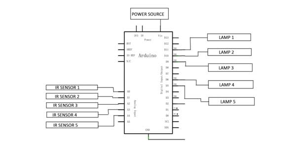
Suppose there are 5 street lights in a road. Each street light is connected to an IR sensor.IR sensor consists of two parts i.e., Infrared Transmitter and Infrared receivers. Infrared transmitter continuously emits the IR rays but it is not received by the infrared receiver. When any vehicle passes through the street light the IR rays gets reflected and is received by the infrared receiver placed beside the IR transmitter. Then the output of IR sensor is given to ADC pin of the arduino. ADC pin is used to convert the analog signal into digital signal. Then comparing the received signal with the threshold value, the supply is given to the next lamp. If the received value is greater than the threshold value then led will glow with the full intensity for next 10 seconds and again come back to the dim state.
IR Sensor Circuit connection
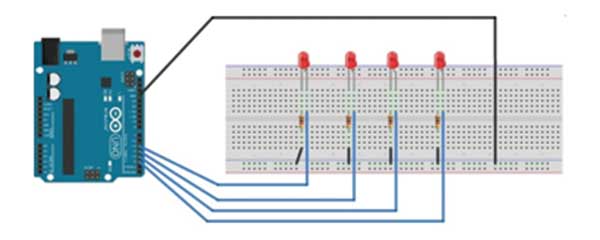
LED Connection with the Arduino
Components Required
1. ARDUINO UNO
2. IR SENSORS

3. LED

4. BREADBOARD

5. MALE-MALE WIRE

6. BATTERY


Explanation of the Circuit
All the 5 IR sensors are connected to the ADC pin of the Arduino i.e., from A0 to A4 and the led’s connected at the pin PWM pins i.e., led1 at 11, led2 at 10, led3 at 9, led4 at 6 and led5 at 5.
When the IR receiver of sensor1 will receive the signal, the Arduino will command lamp2 to glow with full intensity for 10 seconds. In this way whenever any sensor will detect the vehicle then the very next lamp will glow with the full intensity. If there will be no detection of vehicle, then all the lamps will glow in dim state.
Project Source Code
Project Source Code
###
//Program to#include "Timer.h"
int m = -1;
int m2= -1;int m3= -1;int m4= -1;int m5= -1;int sensorValue = 0; // value read from the potint outputValue = 0;int sensorValue2= 0;int outputValue2= 0;int sensorValue3= 0;int outputValue3= 0;int sensorValue4= 0;int outputValue4= 0;int sensorValue5= 0;int outputValue5= 0;Timer t;void throwe(){if(m>0){Serial.print("09A");m-- ;}}void throwe2() {if(m2>0){Serial.print("09B");m2--;}}void throwe3(){if(m3>0){Serial.print("09C");m3--;}}void throwe4(){if(m4>0){Serial.print("09D");m4-- ;}}void throwe5(){if(m5>0){Serial.print("09E");m5--;}}void setup() {// put your setup code here, to run once:pinMode(A0,INPUT);pinMode(11,OUTPUT);pinMode(A1,INPUT);pinMode(10,OUTPUT);pinMode(A2,INPUT);pinMode(9,OUTPUT);pinMode(A3,INPUT);pinMode(6,OUTPUT);pinMode(A4,INPUT);pinMode(5,OUTPUT);t.every(1000,throwe);Serial.begin(9600);t.every(1000,throwe2);Serial.begin(9600);t.every(1000,throwe3);Serial.begin(9600);t.every(1000,throwe4);Serial.begin(9600);t.every(1000,throwe5);Serial.begin(9600);}void loop() {// read the analog in value:sensorValue = analogRead(A0);// map it to the range of the analog out:outputValue = map(sensorValue, 0, 1023, 0, 255);sensorValue2 = analogRead(A1);// map it to the range of the analog out:outputValue2 = map(sensorValue2, 0, 1023, 0, 255);sensorValue3 = analogRead(A2);// map it to the range of the analog out:outputValue3 = map(sensorValue3, 0, 1023, 0, 255);sensorValue4 = analogRead(A3);// map it to the range of the analog out:outputValue4 = map(sensorValue4, 0, 1023, 0, 255);sensorValue5 = analogRead(A4);// map it to the range of the analog out:outputValue5 = map(sensorValue5, 0, 1023, 0, 255);// put your main code here, to run repeatedly:if(outputValue<100){m = 10 ;Serial.print("Y");}if(outputValue2<100){m2=10;Serial.print("Y");}if(m>0){analogWrite(5,250);//Serial.print("t3");}else if(m<=0){analogWrite(5,50);Serial.print("X");}if(m2>0){analogWrite(11,250);}else if(m2<=0){analogWrite(11,50);Serial.print("X");}if(outputValue3<100){m3=10;Serial.print("Y");}if(m3>0){analogWrite(10,250);}else if(m3<=0){analogWrite(10,50);Serial.print("X");}if(outputValue4<100){m4=10;Serial.print("Y");}if(m4>0){analogWrite(9,250);}else if(m4<=0){analogWrite(9,50);Serial.print("X");}if(outputValue5<100){m5=10;Serial.print("t10");}if(m5>0){analogWrite(6,250);}else if(m5<=0){analogWrite(6,50);Serial.print("t11");}t.update();}###
Circuit Diagrams
Filed Under: Electronic Projects

Questions related to this article?
👉Ask and discuss on Electro-Tech-Online.com and EDAboard.com forums.
Tell Us What You Think!!
You must be logged in to post a comment.