Engineers Garage

  • Electronic Projects & Tutorials
    • Electronic Projects
      • Arduino Projects
      • AVR
      • Raspberry pi
      • ESP8266
      • BeagleBone
      • 8051 Microcontroller
      • ARM
      • PIC Microcontroller
      • STM32
    • Tutorials
      • Audio Electronics
      • Battery Management
      • Brainwave
      • Electric Vehicles
      • EMI/EMC/RFI
      • Hardware Filters
      • IoT tutorials
      • Power Tutorials
      • Python
      • Sensors
      • USB
      • VHDL
    • Circuit Design
    • Project Videos
    • Components
  • Articles
    • Tech Articles
    • Insight
    • Invention Stories
    • How to
    • What Is
  • News
    • Electronic Product News
    • Business News
    • Company/Start-up News
    • DIY Reviews
    • Guest Post
  • Forums
    • EDABoard.com
    • Electro-Tech-Online
    • EG Forum Archive
  • DigiKey Store
    • Cables, Wires
    • Connectors, Interconnect
    • Discrete
    • Electromechanical
    • Embedded Computers
    • Enclosures, Hardware, Office
    • Integrated Circuits (ICs)
    • Isolators
    • LED/Optoelectronics
    • Passive
    • Power, Circuit Protection
    • Programmers
    • RF, Wireless
    • Semiconductors
    • Sensors, Transducers
    • Test Products
    • Tools
  • Learn
    • eBooks/Tech Tips
    • Design Guides
    • Learning Center
    • Tech Toolboxes
    • Webinars & Digital Events
  • Resources
    • Digital Issues
    • EE Training Days
    • LEAP Awards
    • Podcasts
    • Webinars / Digital Events
    • White Papers
    • Engineering Diversity & Inclusion
    • DesignFast
  • Guest Post Guidelines
  • Advertise
  • Subscribe

Monitoring voltage of individual batteries connected in series using arduino uno

By EG Projects June 11, 2019

In the previous tutorial i put forward some ways in which batteries connected in series and parallel can be monitored individually. Each battery voltage can be measured separately and smartly through those methods. In this tutorial i thought to implement one method practically to show how it works in the real world. So the scenario is four batteries are connected in series string array. Individual  battery is rated at 12 volts and 100 amperes. Recall in series combination of batteries voltage ads up. So total voltage of 4 batteries connected in series becomes 48 volts and this 48 volt is utilized by your ups to power your house in case of power failure. We are interested in measuring the voltage of each battery. 

Arduino cluster of batteries monitoring – project overview

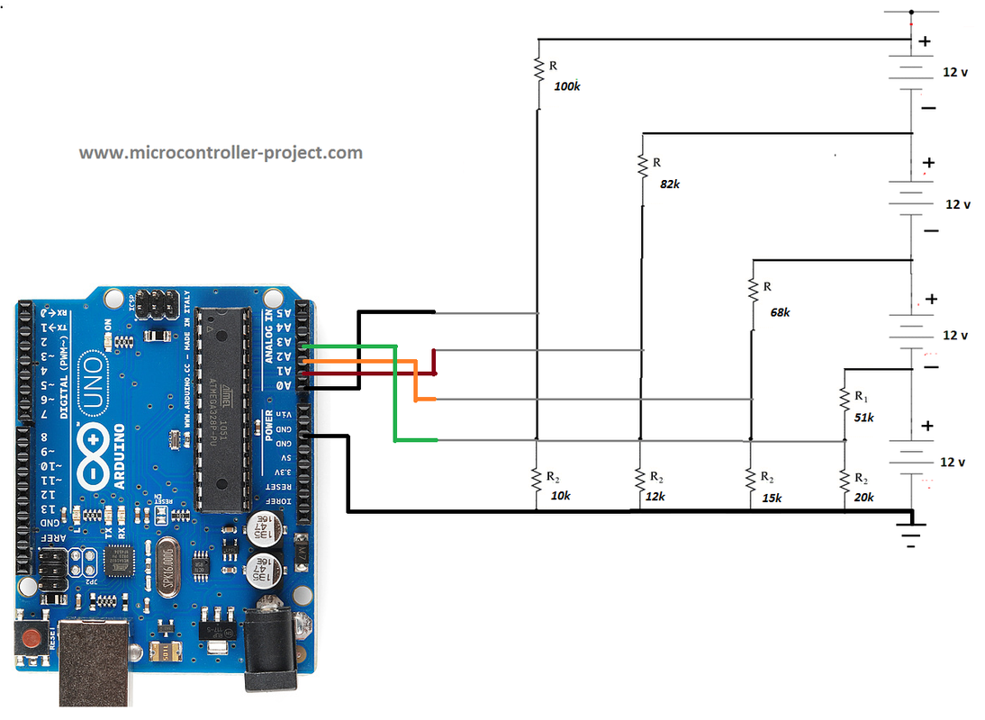
Circuit diagram of the project is below. Four voltage dividers method is used to measure a cluster of four dc batteries. Resistance values of all four voltage dividers are calculated using the technique discussed in the previous tutorial. I highly recommend to take the previous tutorial to know about the technique and how resistance values are calculated in this scenario. Take the below tutorial.       

Methods to monitor string of batteries and formula to calculate the resistance values

Arduino voltage divider battery voltage monitoring – circuit diagram

Arduino uno four analog channels are used to measure four batteries. Note the ground of all the four voltage dividers and arduino are at the same level. If you do not connect the arduino ground with voltage dividers ground then the arduino adc circuit will not complete up. ADC pin will become floating and it will read raw and wrong voltage values. So please make sure to ground all the necessary grounds.  
Arduino uno individual battery monitoring connected in series combination

Arduino uno individual battery monitoring connected in series combination

Arduino series battery monitoring – project code

After circuit coming to the code portion. First i calculated the ratio factors for each voltage divider circuit. R1, R2, R3 and R4 are ratio factors for respective voltage dividers. After ratios comes the readvcc function. This function is actually about configuring the arduino to accurately read its applied power voltage. Imagining arduino works on 5 volts is not necessary all the time. It may be working on 4.8 or 4.7 volts. May be our power supply to arduino is supplying 4.8 volts and we are considering it 5 volts. Usually arduino is powered through laptop/work station USB port and USB port is not truly outputting 5 volts. Its output is between 4.6 to 5.3 volts. Any how the readvcc function give us back the true arduino applied power or power on which it is working. This reading is further used in translating the arduino analog channel read value to actual voltage. 

In the setup function i initialized the serial communication port or arduino serial monitor. Communication speed is set to 9600 bps. In the loop function some variables are initialized for further use in the code. Than arduino reference voltage is calculated. After reference voltage individual analog channels are read one by one. Next the raw values read at the analog channels are converted to 5 volt range. Further the statements   

  B4Voltage = RealBat4V * R4;     //Calculating actual voltages
  B3Voltage = RealBat3V * R3 – B4Voltage;    
  B2Voltage = RealBat2V * R2 – B4Voltage – B3Voltage;
  B1Voltage = RealBat1V * R1 – B4Voltage – B3Voltage – B2Voltage;

are calculating the actual battery voltage. These battery voltages are then printed on the serial monitor of arduino ide. Two seconds delay at the end of the code prevents the arduino from overloading and give its analog channels and serial monitor some rest. You can skip the delay function, code still works. But its wise to give some delay at the end to pause calculations.  
Make battery and arduino uno connections. Now just upload the code to arduino uno. Please make sure to select the right board before uploading the code to arduino uno. Open arduino serial monitor from arduino ide. You will see battery voltages displayed on arduino serial monitor. If you did not see any thing on arduino serial monitor watch for the baud rate and set it to 9600 bps. If still you did not see and thing watch the analog channel connections. Check for every possible error.
The code is modular and can be transferred to any other arduino board with little modifications in code or may require no modification.  
If you are interested in IOT field than the same but little complex project on monitoring battery voltage over WiFi with nodemcu WiFi module is for you. Tutorial link is below

Battery Monitoring over WiFi with nodemcu

Download the project code. Folder contains project .ino file. Please give us your feed back on the project and in case you have any questions or queries. Write them below in comments section.

Arduino Series battery monitor .ino


Filed Under: Arduino Projects, Microcontroller Projects


Next Article

← Previous Article
Next Article →

Questions related to this article?
👉Ask and discuss on EDAboard.com and Electro-Tech-Online.com forums.


Tell Us What You Think!! Cancel reply

You must be logged in to post a comment.

EE TECH TOOLBOX

“ee
Tech Toolbox: Internet of Things
Explore practical strategies for minimizing attack surfaces, managing memory efficiently, and securing firmware. Download now to ensure your IoT implementations remain secure, efficient, and future-ready.

EE Learning Center

EE Learning Center
“engineers
EXPAND YOUR KNOWLEDGE AND STAY CONNECTED
Get the latest info on technologies, tools and strategies for EE professionals.

HAVE A QUESTION?

Have a technical question about an article or other engineering questions? Check out our engineering forums EDABoard.com and Electro-Tech-Online.com where you can get those questions asked and answered by your peers!


RSS EDABOARD.com Discussions

  • surge+EMI filter
  • Input impedance matching network
  • How to preserve hierarchical instance names like \adder_1/U1 in flattened gate-level netlist in Design Compiler?
  • Can anyone provide a guide or tutorial for Candece simulation?
  • Voltage mode pushpull is a nonsense SMPS?

RSS Electro-Tech-Online.com Discussions

  • Can I make two inputs from one??
  • Photo interrupter Connections
  • Is AI making embedded software developers more productive?
  • Why can't I breadboard this oscillator?
  • Cataract Lens Options?

Featured – RPi Python Programming (27 Part)

  • RPi Python Programming 21: The SIM900A AT commands
  • RPi Python Programming 22: Calls & SMS using a SIM900A GSM-GPRS modem
  • RPi Python Programming 23: Interfacing a NEO-6MV2 GPS module with Raspberry Pi
  • RPi Python Programming 24: I2C explained
  • RPi Python Programming 25 – Synchronous serial communication in Raspberry Pi using I2C protocol
  • RPi Python Programming 26 – Interfacing ADXL345 accelerometer sensor with Raspberry Pi

Recent Articles

  • GigaDevice launches GD32C231 MCU series with 48MHz Cortex-M23 core and 64KB Flash
  • Advanced Energy releases 425 W CF-rated medical power supply in 3.5 x 6 x 1.5-inch format”
  • LEM combines shunt and Hall effect sensing in 2000 A current measurement unit
  • What is AWS IoT Core and when should you use it?
  • AC-DC power supply extends voltage range to 800 V DC

EE ENGINEERING TRAINING DAYS

engineering

Submit a Guest Post

submit a guest post
Engineers Garage
  • Analog IC TIps
  • Connector Tips
  • Battery Power Tips
  • DesignFast
  • EDABoard Forums
  • EE World Online
  • Electro-Tech-Online Forums
  • EV Engineering
  • Microcontroller Tips
  • Power Electronic Tips
  • Sensor Tips
  • Test and Measurement Tips
  • 5G Technology World
  • Subscribe to our newsletter
  • About Us
  • Contact Us
  • Advertise

Copyright © 2025 WTWH Media LLC. All Rights Reserved. The material on this site may not be reproduced, distributed, transmitted, cached or otherwise used, except with the prior written permission of WTWH Media
Privacy Policy

Search Engineers Garage

  • Electronic Projects & Tutorials
    • Electronic Projects
      • Arduino Projects
      • AVR
      • Raspberry pi
      • ESP8266
      • BeagleBone
      • 8051 Microcontroller
      • ARM
      • PIC Microcontroller
      • STM32
    • Tutorials
      • Audio Electronics
      • Battery Management
      • Brainwave
      • Electric Vehicles
      • EMI/EMC/RFI
      • Hardware Filters
      • IoT tutorials
      • Power Tutorials
      • Python
      • Sensors
      • USB
      • VHDL
    • Circuit Design
    • Project Videos
    • Components
  • Articles
    • Tech Articles
    • Insight
    • Invention Stories
    • How to
    • What Is
  • News
    • Electronic Product News
    • Business News
    • Company/Start-up News
    • DIY Reviews
    • Guest Post
  • Forums
    • EDABoard.com
    • Electro-Tech-Online
    • EG Forum Archive
  • DigiKey Store
    • Cables, Wires
    • Connectors, Interconnect
    • Discrete
    • Electromechanical
    • Embedded Computers
    • Enclosures, Hardware, Office
    • Integrated Circuits (ICs)
    • Isolators
    • LED/Optoelectronics
    • Passive
    • Power, Circuit Protection
    • Programmers
    • RF, Wireless
    • Semiconductors
    • Sensors, Transducers
    • Test Products
    • Tools
  • Learn
    • eBooks/Tech Tips
    • Design Guides
    • Learning Center
    • Tech Toolboxes
    • Webinars & Digital Events
  • Resources
    • Digital Issues
    • EE Training Days
    • LEAP Awards
    • Podcasts
    • Webinars / Digital Events
    • White Papers
    • Engineering Diversity & Inclusion
    • DesignFast
  • Guest Post Guidelines
  • Advertise
  • Subscribe