Engineers Garage

  • Projects and Tutorials
    • Electronic Projects
      • 8051
      • Arduino
      • ARM
      • AVR
      • PIC
      • Raspberry pi
      • STM32
    • Tutorials
    • Circuit Design
    • Project Videos
    • Components
  • Articles
    • Tech Articles
    • Insight
    • Invention Stories
    • How to
    • What Is
  • News
    • Electronic Products News
    • DIY Reviews
    • Guest Post
  • Forums
    • EDABoard.com
    • Electro-Tech-Online
    • EG Forum Archive
  • Digi-Key Store
    • Cables, Wires
    • Connectors, Interconnect
    • Discrete
    • Electromechanical
    • Embedded Computers
    • Enclosures, Hardware, Office
    • Integrated Circuits (ICs)
    • Isolators
    • LED/Optoelectronics
    • Passive
    • Power, Circuit Protection
    • Programmers
    • RF, Wireless
    • Semiconductors
    • Sensors, Transducers
    • Test Products
    • Tools
  • EE Resources
    • DesignFast
    • LEAP Awards
    • Oscilloscope Product Finder
    • White Papers
    • Webinars
  • EE Learning Center
  • Women in Engineering

Switch Interfacing with Beaglebone Black ( Part 4/15)

By Ashish Vara

This tutorial explains how to interface switch with Beaglebone black where  switch acts as an input device. It is a simple learning tutorial  regarding the use of GPIO pin as an input. Program is written in python script with adafruit GPIO library. It is a not a big deal but it’s necessary to clear fundamental before developing high application.

Required Tools:

  • Beaglebone Black
  • Led
  • Push button
  • 330 Ω Resistor
  • 1 kΩ Resistor
  • Breadboard
  • Female to Female connectors

Setup of Software environment

Install the latest python version in BBB as explained in tutorial How to make first python program with Beaglebone Black. Install the adafruit python-GPIO library named adafruit_BBIO.

Working

It is a simple learning tutorial of Beaglebone black. Here I connected led and switch with GPIO pin of Beaglebone black. When script is being executed, it enters the end of continuous loop. When switch is pressed, led is an ON otherwise it is OFF. Press ctrl+C  to stop the execution of program form SSH command terminal.

Description

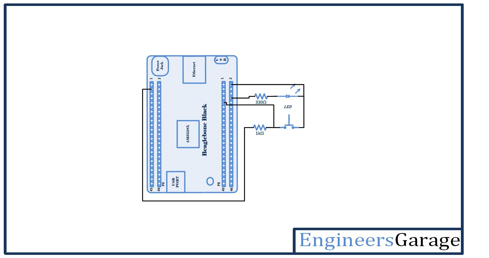
Let’s first prepare the circuit connection. Take a breadboard and provide VCC and ground from BBB to breadboard line. Connect Supply 3.3 V from pin number 3rd of header P9 and ground from pin number 2nd of header P8. Connect the negative terminal of  LED with ground. Connect the 330 ohm resistor with positive terminal of  LED. Connect another end of 330 ohm resistor with pin number 8 of header P8.  Push button has two terminals. Any one of them connects with ground. Provide the VCC 3.3 V through 1k ohm resistor to another terminal of push button. Common end of resistor and push button, connect with pin number 9th of header P8. Provide the supply to Beaglebone black by connecting with PC through USB cable. Now your circuit is prepared.

Image of Beaglebone Black (BBB) Interfacing with Tactile Switch

Fig. 1: Image of Beaglebone Black (BBB) Interfacing with Tactile Switch

Prototype of Beaglebone Black (BBB) and Tactile Switch Interfacing

Fig. 2: Prototype of Beaglebone Black (BBB) and Tactile Switch Interfacing

Open the command terminal and take an access of Beaglebone black through SSH as explained in getting started with Beaglebone black. Create a new file using touch command with .py extension (i.e. led.py). Open the file with any text editor (i.e. nano, vim etc.) and write a code in python language.


Configuration of GPIO pin


Import the GPIO library from adafruit Beaglebone black library by calling following line in program:


import Adafruit_BBIO.GPIO as GPIO


You can define the pin number as a pin number with underscore followed by pin number. (i.e. P8_8). Give  an appropriate name to the pin number.


i.e. BUTTON  =  “P8_9”


Here, I assigned the name BUTTON to pin number 9th oh header P8.


Next, configure the pin as input or output as following function:


 GPIO.setup (Pin number, output/input)


For example, I declared button (pin number 9th oh header P8) as an input by following line:


GPIO.setup (BUTTON,GPIO.IN)


Note: here I declared switch as an input. (led is input device)

You can read the status of input pin by following function:

GPIO.input (pin number)

For example,

GPIO.input (BUTTON)

You can make pin high and low by following function:

GPIO.output (Pin number, High or Low)

For example, I make  LED (pin number 9th oh header P8) as High and low by following line:

HIGH : GPIO.output (LED, GPIO.HIGH)

LOW : GPIO.output (LED, GPIO.LOW)

Run the script from terminal:

Enter the following command with file name from command prompt:

            python filename.py

i.e. python switch.py

Project Source Code

###


# Switch Interfacing Tutorial 
# developed By Ashish vara
# Engineersgarage
 
import Adafruit_BBIO.GPIO as GPIO
 
 
LED1 = "P8_8"
 
BUTTON = "P8_9"
 
 
GPIO.setup(LED1,GPIO.OUT)
GPIO.setup(BUTTON,GPIO.IN)
 
GPIO.output(LED1, GPIO.LOW)
 
 
while True:
 
 
        Button_State = GPIO.input (BUTTON)
 
        if Button_State == 0:
 
                GPIO.output(LED1, GPIO.HIGH)
        else:
 
                GPIO.output(LED1, GPIO.LOW)
 
GPIO.cleanup()
 

###


Circuit Diagrams

Circuit-Diagram-Beaglebone-Black-BBB-Tactile-Switch-Interfacing

Project Video


Filed Under: Electronic Projects


Questions related to this article?
👉Ask and discuss on Electro-Tech-Online.com and EDAboard.com forums.


Tell Us What You Think!! Cancel reply

You must be logged in to post a comment.

HAVE A QUESTION?

Have a technical question about an article or other engineering questions? Check out our engineering forums EDABoard.com and Electro-Tech-Online.com where you can get those questions asked and answered by your peers!


Featured Tutorials

  • Designing Gate Driver Circuit and Switching Mechanism for Modified Sine Wave Inverter – (Part 9/17)
  • Completing Modified Sine Wave Inverter Design with Full Bridge Circuit and Step Up Transformer – (Part 10/17)
  • Designing an Offline UPS – Part (12 /17)
  • How to reduce Switching Time of a Relay – (Part 15/17)
  • Testing MOSFET – (Part 16/17)
  • Driving High Side MOSFET using Bootstrap Circuitry – (Part 17/17)

Stay Up To Date

Newsletter Signup

Sign up and receive our weekly newsletter for latest Tech articles, Electronics Projects, Tutorial series and other insightful tech content.

EE Training Center Classrooms

EE Classrooms

Recent Articles

  • MicroPython – I2C protocol in ESP8266 and ESP3
  • New automotive radar sensor enables reliable in-cabin monitoring system
  • TI breaks ground on 300-mm semiconductor wafer-fabrication plants in Texas
  • New wireless AR Smart Viewer reference design
  • Infineon launches scalable and wireless charging platform with configurable controllers

Most Popular

5G 555 timer circuit 8051 ai Arduino atmega16 automotive avr dc motor display Electronic Part Electronic Parts Fujitsu ic infineontechnologies integratedcircuit Intel IoT ir lcd ldr led maximintegratedproducts microchip microchiptechnology Microchip Technology microcontroller microcontrollers mosfet motor powermanagement Raspberry Pi remote renesaselectronics renesaselectronicscorporation Research samsung semiconductor sensor software STMicroelectronics switch Technology vishayintertechnology wireless

RSS EDABOARD.com Discussions

  • Manifest in Git bitbucket
  • What's the deal with all these "MPPT" IC's with no current sense?
  • Photovoltaic MOSFET Drivers - Voltage Rating
  • Impedance requirement for SDRAM signals
  • A circuit that can adjust a resistance and probing a voltage node

RSS Electro-Tech-Online.com Discussions

  • How to quickly estimate lead acid battery capacity ?
  • IRS2453 the H circuit
  • Ampro 16mm Stylist projector woes.
  • Finally switched to Linux.
  • Multistage BJT amplifier
Engineers Garage
  • Analog IC TIps
  • Connector Tips
  • DesignFast
  • EDABoard Forums
  • EE World Online
  • Electro-Tech-Online Forums
  • Microcontroller Tips
  • Power Electronic Tips
  • Sensor Tips
  • Test and Measurement Tips
  • 5G Technology World
  • About Us
  • Contact Us
  • Advertise

Copyright © 2022 WTWH Media LLC. All Rights Reserved. The material on this site may not be reproduced, distributed, transmitted, cached or otherwise used, except with the prior written permission of WTWH Media
Privacy Policy | Advertising | About Us

Search Engineers Garage

  • Projects and Tutorials
    • Electronic Projects
      • 8051
      • Arduino
      • ARM
      • AVR
      • PIC
      • Raspberry pi
      • STM32
    • Tutorials
    • Circuit Design
    • Project Videos
    • Components
  • Articles
    • Tech Articles
    • Insight
    • Invention Stories
    • How to
    • What Is
  • News
    • Electronic Products News
    • DIY Reviews
    • Guest Post
  • Forums
    • EDABoard.com
    • Electro-Tech-Online
    • EG Forum Archive
  • Digi-Key Store
    • Cables, Wires
    • Connectors, Interconnect
    • Discrete
    • Electromechanical
    • Embedded Computers
    • Enclosures, Hardware, Office
    • Integrated Circuits (ICs)
    • Isolators
    • LED/Optoelectronics
    • Passive
    • Power, Circuit Protection
    • Programmers
    • RF, Wireless
    • Semiconductors
    • Sensors, Transducers
    • Test Products
    • Tools
  • EE Resources
    • DesignFast
    • LEAP Awards
    • Oscilloscope Product Finder
    • White Papers
    • Webinars
  • EE Learning Center
  • Women in Engineering