Although a smaller shape, switches are essentially crucial for any device and hence, a design engineer should consider so many technical things related with a switch, while choosing a switch. Some of the few important terms that are taken care while configuring a switch are operating force, stroke, bounce time, various resistances, dielectric strength, power ratings etc. (Also read Introduction to Different Types of Switches)
Alteration in these mentioned configurations affects the structure and working of switch in every possible manner. Hence, from a hardware designer to an installer, switch configuration plays an important part for any electrical device.The most common specifications found in the datasheet of switches are explained below.
Operating force
The operating force is the maximum fore that should be applied to turn a switch on. The operating force is usually represented in grams. It varies with the kind of the switch and normally less than 1000grams.
If we apply a force greater than the operating force, there is a chance of damaging the metal plates of the switch
Stroke
The stroke can be defined as the maximum distance that the pole metal plate should move so as to make a contact with the fixed metal plates. It is actually the contact gap distance of a switch. They are represented in millimeters.
It is related with the ease of operation of the switch. Switches with low stroke are more preferable.
Bounce time
This is one of the most significant specifications of a switch, usually when it comes to the design of microcontroller based circuits. Bounce time is the maximum time for which the pole metal plates of the switch will keep on bouncing once it made contact with the fixed plate.
It is otherwise called De-bouncing period. De-bouncing is an effect that exists in all kind of metallic switches which can make or break a contact. We normally expect that when we turn on a switch, it simply make contact instantly. But actually it is not like that. The switch continuously make and break contact for a few milliseconds, as if the metal pieces bouncing off from each other after hitting together, like a ball dropped on the floor does. After the de-bouncing time only the switch makes permanent contact

Fig. 1: Diagrammatical Image Explaining Bouncing and Debouncing of Switch
The bounce time is usually represented in milliseconds and usually less than 20ms. The De-bouncing effect can cause wrong interpretation of the state of a switch in microcontroller based circuits. Normally the microcontroller waits for the specified bounce time of the switch before taking a decision about its state.
Hence one should select a switch with as minimum bounce time as possible, so that the valuable operating time of the microcontroller can be saved.
Switch resistance
Switch resistance is referred to the resistance introduced by the switch into the circuit irrespective of its contact state. The resistance will be extremely high (ideally infinite) when the switch is open and a finite very low value (ideally zero) when the switch is closed.

Fig. 2: Graph Showing Typical Switch Resistance Pattern
The above graph represents nothing but, as the contact gap increases the switch resistance also increases.
Contact resistance
Contact resistance is the resistance of a switch when the contact gap is zero.
This is another important specification which has significance in any kind of circuits. An ideal switch is not supposed to introduce any resistance to the circuit while it is on. But in practical cases the switches introduce a resistance called contact resistance into the circuit.
This contact resistance is the inherent resistance of the metal plates which make the contact. Due to this contact resistance a very feeble voltage drop occurs across the switch, which is not at all desired for low voltage circuits. So a designer should select a switch with minimum possible contact resistance.
Normally switches have a contact resistance less than 1 ohm.

Fig. 3: Block Diagram Explaining Contact Resistance in Switches
Stray Capacitance
In open state of any switch, there is only a very small gap between the two metal contacts. Hence it is possible to form a significant capacitance between this contact gap and we call it Stray Capacitance. Usually stray capacitance in the range of Pico Farads is found between the two metals.

Fig. 4: Stray Capacitance in Switches
The stray capacitance has worst effect on high frequency circuits. At very high frequencies a capacitor can act as a short circuit, and hence the switch appears to be closed even if it is physically open.
Hence a designer should select a switch with very low stray capacitance, especially for the design of high frequency circuits.
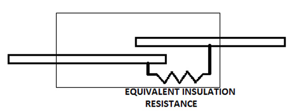
Insulation resistance
Contact resistance is the resistance introduced by the contact metals of a switch into a circuit, in its open (switch off) condition. Ideally switches have infinite insulation resistance, but practically they have a finite very high Insulation resistance.

Fig. 5: Equivalent Resistance in Switches
Since there is existence of a very high resistance even when the switch is on, there is a chance to flow a very feeble current through the circuit. This can cause significant effect in highly sensitive circuits.
A designer should always look for a switch with extremely high insulation resistance.
Dielectric strength
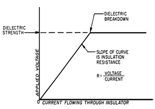
Very high voltages when applied to a switch can cause an arc when the switch is in open state. It occurs due to dielectric break down at the contact gap due to the high voltages. Voltage at which this break down occurs is called Break down voltage.
The dielectric strength of a switch is represented as the maximum voltage that can be applied to a switch without causing a dielectric break down.
This is very significant in high voltage circuits. If voltages greater than dielectric strength of the switch is applied, dielectric break down can occur. This may result in an arc and can permanently damage a switch.

Fig. 6: Graph Showing Votage and Current Relationship in a Switch
The above graph can be read as follows; when the voltage across the open contact increases the current do flows through the switch and obey ohms law. After certain values of applied voltage, the dielectric breakdown occurs and there after the current increases to very high value spontaneously.
Electrical life
It is the maximum number of times a switch can be operated until it fails while it is connected to a live circuit. Simply it is the number of on-offs with load connected to the switch.
After the electrical life of the switch, they fail to operate properly.
Switches generally have an average electrical life of 10,000 cycles.

Fig. 7: Load Versus Life Curve of a Switch
The above graph shows that as the operating lode of the switch increases, the life of the switch decreases.
Hence one should be careful to operate the switch with minimum load as possible for longer operations.
Mechanical life
It is the maximum number of times a switch can be operated without connecting it to any current flowing circuit. Simply it is the number of on-offs without load connected to the switch.
After the mechanical life of the switch, they fail to operate properly. Mechanical life of a switch is always greater than the electrical life.
Switches generally have an average mechanical life of 50,000 cycles.
Electrical operation frequency
It is the maximum possible frequency with which the switch can be operated with a load. In other words it is the rapidity at which the switch can be on-off in a live circuit. It is represented in cycles per minute.
After a specified electrical operation frequency the switch may fail in its operation.
Generally the switches have an average operating frequency of 100 cycles per minute.
Mechanical operation frequency
It is the maximum possible frequency with which the switch can be operated without a load. In other words it is the rapidity at which the switch can be on-off without having connected to a circuit. It is represented in cycles per minute.
After a specified mechanical operation frequency the switch may fail in its operation.
Generally the switches have an average operating frequency of 100 cycles per minute.
Normally for a switch the mechanical operating frequency is slightly greater than the electrical operating frequency.
Vibration
Vibrations can affect the mechanical contact states of a switch. Since the metals can vibrate, an excess vibration of the switch can some time break the contact while it is supposed to be on and sometimes make the contact while it is supposed to be off.
Vibration represents the maximum possible vibration in which the switch can operate without any malfunction.
Normal switches can withstand a vibration of 50Hz. After maximum possible vibration an on switch may turn off or vice versa.
Non-Switch rating
It is the maximum power that can be carried by the switch in its non-switching state. In other words it is the maximum voltage and current possible while the switch remain in it’s stable on state.
When we apply power more than the non-switch rating, it may damage the metal contacts. For high power application a designer prefer the switch with maximum non-switch rating.
Switching rating
It is the maximum power that is allowed to present when the switch is making a contact. If we apply power more than the switching rating, it may damage the metal contacts by generating an arc.
For high power switching application a designer prefer the switch with maximum switching rating.
These are the most common specification which is applicable to any kind of electro-mechanical switch.
Filed Under: Articles


Questions related to this article?
👉Ask and discuss on Electro-Tech-Online.com and EDAboard.com forums.
Tell Us What You Think!!
You must be logged in to post a comment.