In the previous tutorial, the Constant Current (CC) Source of 60 mA and Constant Voltage (CV) Source of 4.2 V were designed using LM317 voltage regulator IC. The constant current source is to be used for constant current mode of the battery charging while the constant voltage source is to be used for constant voltage mode of the battery charging. During the designing of constant current source and the constant voltage source, testing a Li-ion battery before charging it was also discussed. Check out the previous tutorial “Basics of Li-ion battery charging” for learning about the basics of Lithium ion batteries, their charging methods and topologies.
In this tutorial, the switching mechanism for the charging circuit to switch from constant current mode to constant voltage mode is designed and the Li-ion battery charger circuit using linear regulator topology is completed. In the switching mechanism, the detection of battery voltage is done with the help of a microcontroller circuit. The switching mechanism is based on relay circuit which is again operated with the help of microcontroller. By adding the controller based switching mechanism, the charger circuit is completed for single cell Li-ion battery.
Though any microcontroller can be used to design the controller circuit of the switching mechanism, the Arduino UNO is used in this charger circuit as it is widely used prototyping board. It is easy and quick to develop on Arduino because of its large community support and easily available software libraries.
Components Required –

Fig. 1: List of components required for Switching mechanism of Linear Regulator Single Cell Li-ion Battery Charger
Block Diagram –

Fig. 2: Block Diagram of Switching mechanism for Linear Regulator Single Cell Li-ion Battery Charger
Circuit Connections –
In the previous tutorial, a constant current source and a constant voltage source were already designed using LM317 voltage regulator IC. The LM317 is one of the popular positive voltage regulators that comes with features like over voltage protection, internal current limiting, overload protection, low quiescent current (for more stable output) and safe area compensation (its internal circuitry limit the maximum power dissipation so it does not self-destruct). now, it’s time to design a switching mechanism that will allow switching from constant current state to constant voltage state of battery charging by sensing the terminal voltage of the battery.
As per the charging cycle of Li-ion battery, it must charge with constant current for a predefined voltage range. When the battery reaches a pre-set voltage then, it must charge with a constant voltage source. Therefore there must be some intelligent circuitry which can detect the real voltage of the battery and switch the battery between CC and CV mode.
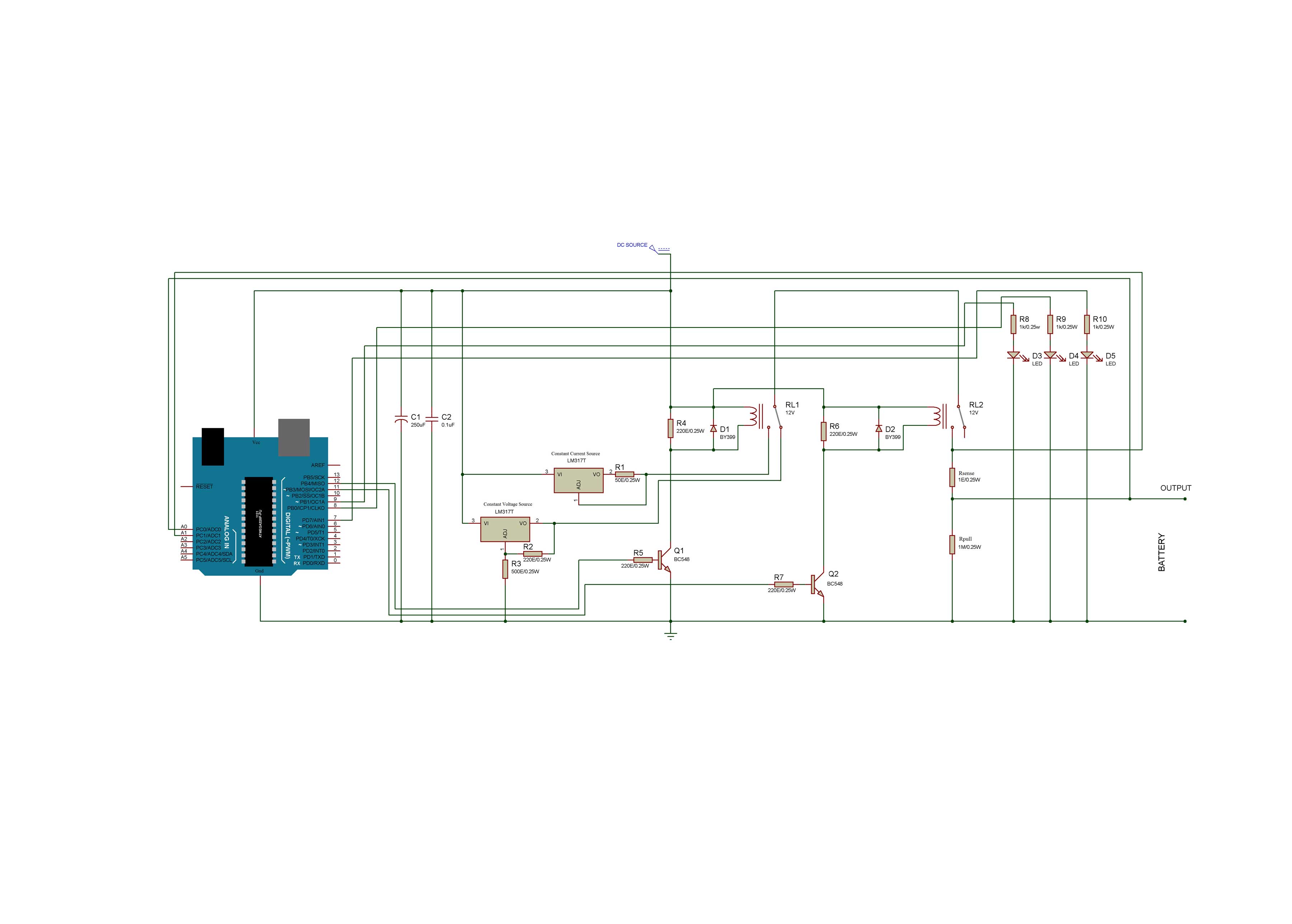
The detection of battery voltage is done with the help of microcontroller (Arduino UNO in this circuit) and switching is done with the help of a relay circuit. The battery that has to be charged has maximum rated voltage of 4.2 V. For charging this battery, a constant current of 60 mA in CC mode and a constant voltage of 4.2 V in CV mode need to be provided. The charger circuit is assembled by connecting the following components –
Relays – For switching the CC and CV circuit mechanical relays are used in this circuit. There are two relays (shown as RL1 and RL2 in circuit diagram) used in the circuit. The relays one end of energizing pin is connected to 12V supply and another end at the collector of transistors Q1 and Q2.
Switching Transistors – The relay gets triggered when the transistors (Q1 and Q2) switches ON. The transistor Q1 and Q2 are interfaced with the pins 12 and 11 of the Arduino board respectively. The transistors are used as high side switch in the circuit.
Diodes – The diodes D1 and D2 help in discharging the relay coil current when they are switched OFF. These diodes are called Fly back diodes or freewheeling diodes.
Current sense resistor – For sensing the charging current, a small value resistor Rsense (1 ohm) is used. This resistor is connected to the NO pin of the relay R2. In the circuit, this resistor takes a maximum drop of 60 mV so it is better to take the resistor of value as small as possible. The power rating of the resistor Rsense can be calculated as follow –
Maximum current that has to flow from the resistor Rsense is 60mA.
So, Power =(maximum current across Rsense)2*Rsense
Power = (0.06*0.06)*1
Power = 3.6 mW
So as per the availability, a resistor having power rating of 0.25 W can be used for Rsense. The current sense resistor is interfaced to the pin A1 of the Arduino while the pin A0 of the Arduino is interfaced to the output terminals of the charger circuit for sensing the battery voltage.
Pull-down resistor – At output a high value of pull-down resistor Rpull (1 MΩ) is used. This resistor helps the circuit to remain in ideal mode. This resistor is used to ground the unwanted spikes or noise at the output when the battery is not connected to the output. So the ADC pin of the microcontroller will not sense abrupt or noise signals in no battery condition.
Microcontroller – Arduino UNO is the microcontroller board used in the circuit. The analog pin of the controller senses the current as well as the voltage of the battery. So, the controller helps in triggering the relays ON and OFF which switches the output of CC and CV circuits. The sensing of voltage and current from the analog pins is managed by the Arduino Sketch. The voltage and current levels of the battery are digitized in the controller and compared with maximum rated values to determine switching point. When circuits are to be switched, the controller changes digital logic at the pins connected to the transistors to activate the relays.
Download and check out the Arduino Sketch to learn how it provides the software based intelligence to switch the CC and CV circuits programmatically.
Indication LEDs – There are three LEDs connected in the circuit to indicate the charging state of the circuit. When the charger circuit is working in CC mode, white LED (shown as D3 in the circuit diagram) starts glowing. When the charger circuit is working in CV mode, green LED (shown as D4 in the circuit diagram) starts glowing. When the battery is fully charged, red LED (shown as D5 in the circuit diagram) starts glowing. These LEDs are controlled by the Arduino board and depending upon the real voltage of the battery sensed by the controller, it switches ON one of these LEDs by passing a HIGH logic at the interfacing pin. The while LED, green LED and Red LED are interfaced to the pins 7, 8 and 9 of the Arduino board respectively.
Capacitors – The capacitor C1 at the input of voltage regulator can handle mains noise. The ceramic capacitor C2 in parallel with this C1 is used to reduce the ESR. The capacitor used in the circuit must be of higher voltage rating than the input supply voltage. Otherwise, the capacitors can start leaking the current due to the excess voltage at its plates and will burst out. It must be made sure that the filter capacitors are discharged before working on a DC power supply. For this, the capacitors must be shorted with a screwdriver wearing insulated gloves.
How the circuit works –
As per the algorithm when the battery voltage is in between 3 V to 4 V then the battery has to be charged by constant current source. When the voltage of the battery reaches to 4 V, then, it should charge with a constant voltage source of 4.2 V.
This charging circuit operates in four states –
Ideal state – Initially, 12V DC is applied to the charging circuit and any battery is not connected at the output. In this state, the circuit remains in Ideal State. The analog pin of the controller senses zero volts at the output and does not trigger any of the relays.
Constant Current State – When the battery is connected to the circuit whose real voltage is in between 3V to 4 V, then the microcontroller triggers the transistors Q1 and Q2. This activates the relay R1 as well as R2 and the battery is connected to the CC circuit. The battery now starts charging with a constant current of 60mA and white LED is switched ON. When the battery voltage reaches to 4V then the battery should switch to CV state.
Constant Voltage State – When Li-ion battery voltage reaches to 4 V then the microcontroller sense it through pull down resistor and switches the transistor Q1 OFF. This de-energizes the relay R1 and the battery is then connected to CV circuit. This circuit charges the battery with a constant voltage of 4.2 V and Green LED is switched ON. The microcontroller continuously monitor the charging current or battery current in this state.
Termination State – When the charging current is approximately 10% to 20% of the 60 mA then the battery is said to be fully charged. In this circuit, 10mA of charge current is set as Cut-OFF point for battery charge termination. When the battery current is less than 10mA then the microcontroller switches OFF the transistor Q2 and deactivates the relay R2. This disconnects the battery from CV circuit and Red LED is switched ON to indicate that the battery is fully charged.
Programming Guide –
The Arduino Sketch manages to sense the battery voltage and battery current and according it changes the charging state by switching the relays. In the Arduino sketch, first off all, the circuit connections are represented by defining the variables for them.

Fig. 3: Screenshot of Arduino code used for changing the charging states
For sensing battery voltage, SenseVoltage() function is defined. In the function, the battery voltage is sensed using analogRead() function and the digital reading is returned as float. For sensing battery current, senseCurrent() function is defined. The function works same as the senseVoltage() function except that the associated pin has current sensing resistor connected to it.

Fig. 4: Screenshot of Arduino Code used for sensing voltage
The Arduino pins are set as digital input or output using pinMode() function in the setup() function and default logics are passed to them. The setup() function runs only once when the board is initially powered on.

Fig. 5: Screenshot of setup function in Arduino Code for Switching Mechanism of Linear Regulator
The charging state of the battery is determined using a Flag variable in the code.

Fig. 6: Screenshot of Flag Variable in Arduino Code for Switching Mechanism of Linear Regulator
According to the battery state, the relays are triggered by setting digital logic at the controller pins connected to the switching transistors. The change of digital logic is done by a switch statement in the code which has Flag variable as the switching argument.

Fig. 7: Screenshot of digital logic in Arduino Code for Switching Mechanism of Linear Regulator
This completes the Arduino sketch. Check out the complete code and compile it to an Arduino board for testing.
Testing the circuit
For testing the charger circuit, a Li-ion battery of nominal voltage 3.7 V is charged by it. Initially, the battery voltage (Vbat) is measured to be 3.84 V and the following observations are noted while charging the battery –

Fig. 8: Table listing output characterstics of Li-ion Battery Charger
From the above observations, it can be analyzed that the battery is charging very slowly. This is due to the less charging current (only 60 mA) in the constant current mode. If the charging current is increased then the battery takes less time to charge. The charging current of the battery in CC mode can be increased as per the battery standards. This decreases the charging time of the battery.
The charger circuit designed using linear regulator has the following features –
Reverse battery polarity protection – In the circuit, relays provide the isolation when the battery is connected in reverse polarity.
Back current protection – When charging circuit is OFF and the battery is still attached at the output, then there can be a reverse flow of current from the battery to the charger circuit. So, the relay R1 provides the isolation and protects the circuit from the back current.
Automatic charge termination – The controller is programmed to cut off the CV circuit as well once the battery voltage reaches 4.2 V. So, there is an automatic charge termination avoiding any overcharging of the battery.
Visual Indication – There are LEDs interfaced in the circuit to indicate the charging state of the battery. When the battery is charged between 50% to 90% and the charger is operating in constant current mode, white LED is switched on. When the battery is charged 90% or above and the charger is operating in the constant voltage mode, green LED is switched on. When the battery is fully charged, red LED is switched on. All these LEDs are switched by the controller depending upon the real voltage of the battery sensed by it.
This charger circuit is simple to design and only needs basic electronic components for assembling. The program code used on the Arduino board is also simple and straight forward. Though this charger circuit has certain limitations.
The charging time taken by the circuit to charge the battery is more as the charging current set in the constant current mode is less. The charging time can be reduced by increasing the charging current in CC mode. For learning how the charging current can be increased in the CC mode, check out the previous tutorial, in which the constant current and constant voltage source circuits were designed. This circuit has become quite bulky due to use of mechanical relays. Also, the circuit is designed to operate in only constant current and constant voltage state. The charger circuit does not operate in trickle charge state which is meant to charge the battery when its real voltage is below 3V. So, this charger circuit should be used to charge a Li-ion Battery whose voltage is above 3V.
While assembling the circuit, it is important to take care of certain precautions. For safety reasons, the Li-ion batteries must always be charged with 0.5 C to 0.8 C charge rate. The relay voltage should be less than the input voltage applied for triggering the relay. The Flyback diodes (D1 and D2) should be used across both the relays for preventing the circuit from any back current. A resistor of appropriate power rating must be used for Rsense otherwise a resistor of lower power rating can get damaged from high current. The Arduino board can sense the minimum voltage of 5 mV. Therefore the current sensing resistor must be wisely chosen, so that voltage across it does not drop below 5 mV in any of the charging states. It must be taken care that he output terminals of the charger circuit does not get shorted accidentally. Otherwise, it will cause the battery terminals to short too and this may burst the battery into flames. So, there can be a serious hazard if the battery terminals are shorted even by mistake. There should not be any loose connections in the circuit otherwise, there can be no voltage or abrupt voltage at the output.
While assembling the circuit, it is also important to keep certain precautions specially while interfacing components with the Arduino board. It should be made sure that the back surface of the controller board does not touch any metal surface since it can flow small current beneath it and may damage the board. The voltage supply to the Arduino UNO must not exceed beyond 12V. So a regulated DC supply should be used to power the Arduino board. The controller board works on DC supply only. So even if the primary source of power for the charger circuit is AC mains, then it must be stepped down by a transformer, rectified by a bridge circuit and regulated by a voltage regulator IC like 7812. While compiling code, correct board must be selected in the Arduino IDE. The selection of board can be done by navigating to Tools->Boards->select option. While uploading the code USB connector should not be removed from the PC when the sketch is uploading on the board even if it may be taking time.
You may also like:


Project Source Code
###
//Program to Author - Diksha *Linear regulator single 3.7V Li-ion battery charger *Charges the battery in Constant Current(CC) with 60mA current and in Constant Voltage(CV) mode with 4.2V */ /*IN/OUT Pin connection *Sense battery voltage - A0 *Sense resistor voltage - A1 *BJT for Switching state relay - 11 *BJT for isolation relay - 12 *CC mode LED - 9 *CV mode LED - 8 *Fully charged battery LED - 7 */ // They're used to give names // to the pins used: #define analogInPin_V_bat A0 // Analog input pin at battery positive #define analogInPin_I_bat A1 // Analog input pin at sense resistor #define switch_pin 11 // switching state relay #define isolation_pin 12 // Isolation pin relay //#define PowerSupply 10 // PowerSupply relay #define CC_LED 9 // LED indication for cv mode #define CV_LED 8 // LED indication for cc mode #define BAT_FULL_LED 7 // LED indication for FULLY CHARGE battery int Flag = 0; // variable to set CC and CV mode /////function declaration float senseVoltage(void); // Battery Voltage sensing float senseCurrent(float); // Charging current sensing /////Function definition /* * Function Name - senseVoltage * Function to read voltage of battery * Input parameters - none * Return - float */ float senseVoltage(){ ///read analog voltage int senseV_bat = analogRead(analogInPin_V_bat); // map it to the range of the analog out: float V_bat =(senseV_bat/1024.0)*5.0; Serial.println("currentBatteryVoltage"); Serial.println(V_bat); return(V_bat); } /* * Function Name - senseCurrent * Function to read charging current of battery * Input parameters - float * Return - float */ float senseCurrent(float currentBatteryVoltage){ ///read analog voltage float senseResistor = analogRead(analogInPin_I_bat); // map it to the range of the analog out: float senseResistorVoltage =(senseResistor/1024.0)*5.0; float actualResistor_Voltage = (senseResistorVoltage-currentBatteryVoltage); ////calculating current from voltage difference of sense resistor float I_bat = (actualResistor_Voltage)*1000; //print at serial monitor Serial.println("currentBatteryVoltage"); Serial.println(currentBatteryVoltage); Serial.println("senseResistorVoltage"); Serial.println(senseResistorVoltage); Serial.println("actualResistor_Voltage"); Serial.println(actualResistor_Voltage); Serial.println("I_bat"); Serial.println(I_bat); return(I_bat); } void setup() { // initialize serial communications at 9600 bps: Serial.begin(9600); /////////set IN/OUT pins pinMode(switch_pin,OUTPUT); pinMode(isolation_pin,OUTPUT); pinMode(CC_LED,OUTPUT); pinMode(CV_LED,OUTPUT); pinMode(BAT_FULL_LED,OUTPUT); //initially both relays are OFF digitalWrite(switch_pin,LOW); digitalWrite(isolation_pin,LOW); } void loop() { uint8_t BatteryState=0 ; // Variable to keep track of battery state //Every time eet these pin low digitalWrite(isolation_pin,LOW); digitalWrite(CC_LED,LOW); digitalWrite(CV_LED,LOW); //////////****read the analogvalues float batteryVoltage = senseVoltage(); //return battery voltage float batteryCurrent = senseCurrent(batteryVoltage); // return battery charging current if(Flag == 1) { // After CC mode enter in CV mode BatteryState = 2; Flag = 0;}// Battery enter in CV mde after CC mode else if(Flag == 2){ while(batteryVoltage>=4.0){ batteryVoltage = senseVoltage(); //check for when battery is removed or battery is discharged below 4V if(batteryVoltage <4){ Flag = 0; digitalWrite(BAT_FULL_LED,LOW); break;}}}// battery fully charged scanning for battery removed or not else if(batteryVoltage < 3.0){ //do nothing }// No Battery or bad battery,Ideal state else if(batteryVoltage<4.0 && batteryVoltage>3.0){ digitalWrite(isolation_pin,LOW); BatteryState = 1; }//charge battery in CC MODE else if(batteryVoltage >= 4.0){ BatteryState = 2; }//charge battery in CV MODE /////////////*****MODE SELECT****/////////// switch(BatteryState){ case 1: // CC MODE ///Switch ON CC mode LED and trigger relay digitalWrite(isolation_pin,HIGH); digitalWrite(switch_pin,HIGH); digitalWrite(CC_LED,HIGH); Serial.println("CC mode"); //when battery voltage is in between 3V and 4V enter in while loop while(batteryVoltage <4.0 && batteryVoltage>=3.0){ batteryVoltage = senseVoltage(); //check for when battery is charging in CC mode if(batteryVoltage>=4.0){ digitalWrite(isolation_pin,LOW); //delay to compensate switching time of relay with software delay(100); Flag = 1; digitalWrite(CC_LED,LOW); break;} //check for when battery is removed else if(batteryVoltage<3.0){ digitalWrite(isolation_pin,LOW); digitalWrite(switch_pin,LOW); digitalWrite(CC_LED,LOW); Serial.println("EXIT "); //delay to compensate switching time of relay with software delay(100); break;} } break; /// exit case 1. case 2: // CV MODE ///Switch ON CV mode LED and trigger relay digitalWrite(isolation_pin,HIGH); digitalWrite(CV_LED,HIGH); Serial.println("Cv mode"); batteryVoltage = senseVoltage(); //when battery voltage is in 4V enter in while loop while(batteryVoltage >=4.0 ){ batteryVoltage = senseVoltage(); batteryCurrent = senseCurrent(batteryVoltage); //check for when battery is charging in CV mode if(batteryCurrent < 10){ digitalWrite(isolation_pin,LOW); //delay to compensate switching time of relay with software delay(100); digitalWrite(CV_LED,LOW); digitalWrite(BAT_FULL_LED,HIGH); Flag = 2; Serial.println("Battery charged"); break;} //check for when battery is removed else if(batteryVoltage<3.0){ digitalWrite(isolation_pin,LOW); //delay to compensate switching time of relay with software delay(100); digitalWrite(CV_LED,LOW); break;} } break; /////end of switch case 2. } }###
Circuit Diagrams
Project Video
Filed Under: Electronic Projects, Featured Contributions
Filed Under: Electronic Projects, Featured Contributions

Questions related to this article?
👉Ask and discuss on Electro-Tech-Online.com and EDAboard.com forums.
Tell Us What You Think!!
You must be logged in to post a comment.