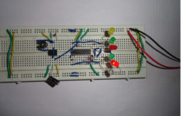
The circuit is used for decoration purpose or as an indicator. Flashing or dancing speed of LED’s can be varied with the help of variable resistor and various dancing pattern of light can be formed by slight change in the circuit. In this circuit 6 LED’s moves in one direction then again flow the opposite direction than previous. The circuit is based on two IC’s namely NE555 and CD4017 with few more components. 555 timer IC wired as an astable oscillator. In this circuit NE555 astable generates a clock for the circuit which provide a oscillating wave to the output pin 3 of IC1. You can vary the speed of oscillation with the help of VR1. The frequency of oscillation of 555 timer can be calculated by f=1.44/(R1+2*(VR1)*C1) and CD4017 is a CMOS counter/ divider IC. It take clock signal from the clock input and turn on the 10 output in sequence, each time when it receives clock input pulses. It is the most popular IC and extremely useful in various project like Light Chaser, Matrix Die. In order to understand the working of IC one must know about its individual pin.
LED Based Pendulum Circuit
The circuit is based on two IC’s namely NE555 and CD4017 with few more components. where 555 timer IC is wired as an astable oscillator. CD4017 is a CMOScounter/ divider IC which takes clock signal from the clock input and turns on the10 output in sequence, each time when it receives clock input pulses. It is the most popular IC and is extremely useful in various project like Light Chaser, Matrix Die.The circuit is based on two IC’s namely NE555 and CD4017 with few more components. where 555 timer IC is wired as an astable oscillator. CD4017 is a CMOS counter/ divider IC which takes clock signal from the clock input and turns on the10 output in sequence, each time when it receives clock input pulses. It is the most popular IC and is extremely useful in various project like Light Chaser, Matrix Die.
Traffic Control System
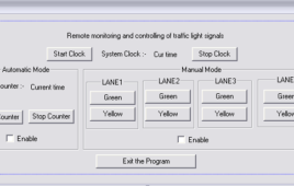
Actually this is remote traffic monitoring and control system in which a police man can control the flow of traffic from a remote location through his computer. He can generate all three traffic signals (red, green & yellow) on a click of mouse only. Also he can divert the flow of traffic by monitoring it…
Wireless DC Motor Speed Control using IR and IC555
This is a very interesting application. We shall vary the speed of DC motor from a remote place without any wire connection. I am using PWM (pulse width modulation) method to very the speed of DC Motor. To make it wireless I am using IR transmitter and IR sensor. There are two sections in the circuit 1) PWM generator with IR modulator and 2) IR receiver and motor driver. Transmitter generates PWM wave of 50 Hz (20 ms) and modulates it over 38 KHz frequency. The IR sensor on receiver side will demodulate the PWM wave and drives the DC motor.
Wireless Stepper Motor Speed Control using Laser and IC555
An interesting project explaining how can one control speed of a stepper motor from a remote place without using any wires. A LASER and LDR are used for this purpose. From the transmitter, low frequency pulses are sent to the receiver using LASER diode. On the receiver side, a LDR will receive these pulses which will further trigger mono stable multi-vibrator to regenerate same pulses. These pulses will drive the stepper motor through driver circuit. So as anyone changes pulse frequency from transmitter, the stepper motor speed will change accordingly. The project uses a pulse generator, LASER, LDR, monostable multi-vibrator, current drive, stepper motor, counter and OR gates.
Coin Toss/Flip Simulator Circuit
The Coin Flip Simulator is an interesting electronic project which can be used to conduct a toss between two teams or individuals. It is a decision maker used [[wysiwyg_imageupload::]]at the places where someone is not able to make up the mind. When a button is pressed, the head and tail LEDs start flashing alternatively at a high speed. The speed slows down and it finally stops with only one LED glowing which determines the final result. In this project 555 timer is wired in astable mode. 7473 IC contains two independent positive pulse triggered J-K flip-flops with complementary outputs. When the clock is LOW, no output is received. When clock is at positive transition, the data from J and K gets transferred from slave to the master. When the clock is at HIGH the J and K inputs become disabled and with negative transition the data from the master gets transferred to the slave.
Night Lamp with Timer for Stairs
This circuit is based on the phenomenon of Push-ON and Auto-OFF. This means that when the circuit is switched ON, it will remain ON for specific period of Night Lamp with Timer for Stairs>time and then it will turn OFF automatically. Again to switch ON the circuit the user has to push the button ON…
Touch Switch for On/Off High Voltage Electrical Equipments
Touch switch with a 555 timer has been built long before. The basic idea is the 555 timer should be configured in monostable mode and the TRIGGER terminal of the 555 timer is left open as TOUCH lead. The discrepancy in using the design is switching both ON and OFF intentionally i.e. once the lead…
Touch switch using monostable mode of 555 timer IC
This project demonstrates the principle and operation of application based on touch sensor. The circuit is divided into three parts: Input, 555 timer and output. A [[wysiwyg_imageupload::]]touch plate is used for the input and output can be seen across an LED or a buzzer. Some application of the circuit include touch based blinking lights, touch buzzer, touch switch etc.This circuit can be used in the following applications: 1. To detect stray voltages produced by mains or to detect electrostatics build up in a room.2. To make touch buzzers. 3. To implement touch switches like for a bell.


