This project uses DTMF technology to control home appliances. DTMF stands for Dual Tone Multi Frequency.This DTMF based system can control home appliances via mobile phone communication from anywhere around the world.This facilitates the user to operate anything on his fingertips.It requires two cell phones to operate properly; one of them will always remain in touch with the circuit and another to place a call on that phone.
Lasered Security System
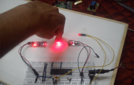
This system for security uses the combination of LASER light and LDR. The LDR module has an onboard potentiometer to adjust the sensitivity of LDR, so that it only senses laser light falling onto it.The concept is quite simple and similar to what we see in movies where antique, priceless ornaments are protected under laser lights.As someone crosses these lights, an alarm runs on to indicate unauthorised presence. This project works similarly.In normal conditions, where there is always laser light falling on the LDR, the LDR module always gives a high signal to microcontroller
Line Follower Robot

Line follower robot is a bot which can follow a particular line. Its a very good project to start with, for people who are interested in robotics and embedded systems.In this case, it will follow a black line on a contrasting white background surface.This bot comprises of a sensor section, driver section and a microcontroller to process the sensor values and correspondingly operate the motor driver section.Sensor section consists of IR sensors (2 in this case)Driver section involves the working of geared DC motors (via L293D IC)
Industrial Temperature Control System

Temperature controllers are used in most of the manufacturing industries. The industries like textile mill, pharmaceutical industry, oil refinery etc. all requires temperature controller. The temperature controllers are used to maintain constant temperature of process or plant or any material. In such temperature controller system there is one reference temperature called set point or set temperature that is the desired temperature that must be maintained. This reference temperature is set by external means. Also it can be always adjustable according to requirements. Once this temperature is set the system tries to maintain it by sensing the current temperature and controlling it using heater, cooler or compressor etc.
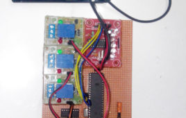
AC Motor Speed Control using RF Remote
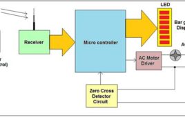
Controlling speed of AC motor is required in industries as well as in domestic use. In industries the required motion control is achieved by controlling speed of big and heavy AC motors. They use variable frequency drives (VFD) for speed control. In some other applications like fan, blowers, heaters etc another method for speed control is used that is phase angle control. By varying phase angle, the current supplied to motor can be varied. And by varying supplied current the speed of motor can be varied.In domestic application the phase angle control method is used. The best example is fan regulator. In domestic fan regulator DIAC and TRIAC are used to vary phase angle of fan motor. This is very easiest method to vary AC motor speed.
Motor Protection against Single Phasing and Overheating
In the present context, there are many industries, mills, research and development centers, public and private sectors in different fields. For example steel sector, Oil sector, spinning mills, elevators, escalators, Trains etc. All of the industries and other various sectors employ Electrical motors and drives. Most of the electrical motors are designed for three phase, 50Hz (in India) supply. As compared to DC motors, these three phase motors are less expensive and can be started easily using D.O.L or Star/delta starters. Three phase induction motors are very sensitive and get damaged, whenever they are subjected to several abnormal conditions like Single-phasing oroverheating.In Industrial three phase loads, whenever any one of the phase of a balanced three phase supply fails to function, the remaining two phases act as a single phase source. Thus, a three phase load is driven by a single phase supply. This phenomenon is known as Single Phasing. It may cause due to line fuse blown off, terminal contacts broken due to ageing or line wire broken. This may cause possibility of fire, vibration in motors, fluctuation of speed, burning of motor winding.
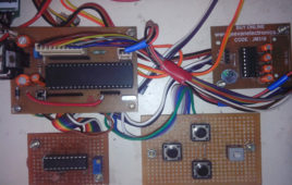
Real Time Clock using 8051 Microcontroller and RTC IC DS1307
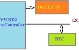
A Real Time Clock (RTC) is basically just like a watch – it runs on a battery and keeps time for you even when there is a power outage. Using an RTC, you can keep track of long timelines, even if you reprogram your microcontroller or a power plug.The real time clock (RTC) is widely used device that provides accurate time and date for many applications. Many systems such as IBM pc come with RTC chip on mother board.RTC chip uses an internal battery which keeps time and date even when the power is off. In some microcontrollers have inbuilt RTC while others requires interfacing.Most widely used RTC chip is DS1307 from Dallas Semiconductor. It uses external lithium battery of 3V to keep operating for over maximum 10 years in the absence of external power supply.DS1307 uses CMOS technology to keep power consumption low. According to datasheet of DS1307 from Dallas, it keeps track of “Seconds, Minutes, and Hours, Day of week, Date, Month and Year”.
Tachometer using microcontroller

Here is a trial of building a tachometer using AT89S52 Microcontroller. This is a digital tachometer which works using infrared rays. The tachometer designed here can measure rotational speed up to 4200 rpm which is sufficient for small scale use. If the speed goes beyond 4200 rpm, it gives a message on the display screen as “OUT OF RANGE”.Take out the wheel of a damaged optical mouse and make a hole at the center of the wheel. Put the steel rod at the hole and glue it tightly so that the rod and the wheel rotate simultaneously. Make the plywood frame as shown in figure and screw the screw bearings on both sides so that the rod with the wheel can be mounted. After mounting the rod (with the wheel) on the screw bearings, try rotating the wheel with your finger. While rotating, the rod should have a minimum friction with the screw bearings.
Keil interfacing programs for 8051
After going through sample programs in keil now, you should be aware of how to write simple codes in C language for 8051. So now, let us see some more programs in C language for 8051. These programs are interfacing programs means different peripheral devices are connected with 8051 and we have to write the C…
Sample Programs in Keil for 8051
Keil is a German based Software development company. It provides several development tools like • IDE (Integrated Development environment) • Project Manager • Simulator • Debugger • C Cross Compiler , Cross Assembler, Locator/Linker Keil Software provides you with software development tools for the 8051 family of microcontrollers. With these tools, you can generate embedded applications for the multitude of…
Simple Programs in 8051 Assembly Language
Here some simple assembly language programs for 8051 microcontroller are given to understand the operation of different instructions and to understand the logic behind particular program. First the statement of the program that describes what should be done is given. Then the solution is given which describes the logic how it will be done and…
8051 Instruction Set
Here one can find complete instruction set of 8051 microcontroller. Complete information regarding each instruction like operational explanation, addressing mode, no. of byte occupied, no. of cycles used etc is given. So just, go through it. It’s a ready reference. The complete 8051 Instruction Set or all 8051 instructions are broadly classify in to…
Differential Relay to protect System from Negative Phase
The combined protection relay is one of the relays, which basically designed to protect the user device from negative phase sequence, single phasing and also the power distribution line with the help of a differential relay. The negative phase sequence relay basically protects the devices against the reverse phase sequence and also against the unbalance phase sequence generated due to unbalance loading. Single phasing relays protect the device against the phase failure. The differential relay protects the zone of the transmission line.The specialty in this project is the design is made on 89c51 micro controller, which is faster and controls all the relays. This is static relay so no much mechanical movement is there. The response time is very fast and can be programmed for any value. The great advantage of programming is available to the user.
Interfacing ADC0808 with Serial port (RS232) using interrupt clock from 8051 microcontroller (AT89C51)- (Part 27/45)
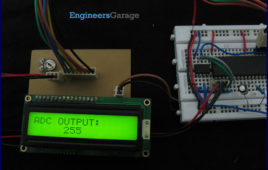
In many applications data collected from multiple sensors is transmitted to PC for display or further analysis. The conversion of data from analog to digital form is done using an ADC. The digital data from the ADC is transferred to the computer using serial port. This circuit demonstrates the principle and operation of interfacing an ADC0808 with serial port of PC using the microcontroller AT89C51. The circuit is divided into three parts: ADC, controller and serial port. This circuit can be used as an intermediate circuit in many applications.ADC0808 which is an 8-bit resolution ADC has eight input channels i.e., it can take a maximum of eight analog inputs. The circuit uses the first analog input pin to take the analog input signals from the preset. To provide clock input to the ADC, Timer0 is used in interrupt enabled mode to generate a clock of frequency 500 KHz. To enable the Timer0 in interrupt enable mode, the register IE is loaded with the value 0x82. Every time the timer completes the counting, pin P1.2 toggles its state.
How to interface Serial ADC0831 with 8051 Microcontroller (AT89C51)- (Part 30/45)
ADC is an electronic device which converts analog signals into its corresponding digital signal. This article demonstrates the principle, operation and interfacing of 8-bit serial ADC0831 with 8051 microcontroller.ADC0831 is an 8 pin IC with 8-bit serial data output (for more detail about ADC0831 refer to Interfacing ADC0831 with ATmega16). To receive the output from ADC high to low pulse is given at CS (chip select) pin of ADC form controller. ADC requires delay of two clock pulses before starting data conversion. At the second clock cycle, ADC sends a ‘0’ bit to the controller which indicates that the upcoming bits are the data bits.ADC needs eight clock pulses to send 8-bit digital output. This digital data is received bit by bit and stored in a variable. The data is converted to its corresponding ASCII value and sent to LCD for display. The connections of LCD with microcontroller are shown in circuit diagram. The analog signals are generated by at a variable resistance (preset) which is connected to input pin of ADC0831.
How to create custom characters on 16×2 LCD using 8051 microcontroller (AT89C51)- (Part 10/45)
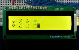
The commonly used 16×2 LCD can also display custom made characters besides numbers, alphabets & special characters. Any character can be made to appear on a 5×8 pixel matrix element without knowledge of its ASCII value. The idea explained here demonstrates the principle and operation of a simple LCD custom character display using 8051 microcontroller (AT89C51). When the ASCII code for any character, say ‘A’, is sent to be displayed on LCD module, the module’s controller looks up the appropriate 5×8-pixel pattern in ROM (read-only memory) and displays that pattern on the LCD. There are 8 symbol locations where a custom character can be stored as shown in the following right table. These locations will have a particular bitmap layout corresponding to the custom character. To display an arrow sign, the bitmap values are mapped to a base address location, say 64 (ASCII code 0).
Typing Assistant based on 8051 microcontroller
Just as a PC software, that are being used in PCs to increase the typing skill and speed in a computer keyboard, this device has been developed to do the same job but without any PC. The device has a PS/2 keyboard port to connect a computer PS/2 keyboard (not an USB keyboard) and a LCD screen to display. When the circuit is assembled and programmed, a PS/2 keyboard has to be connected at the PS/2 socket provided in the device and it then serves as a portable TYPING ENHANCER. It needs only a 5V power supply and nothing else. It has no connection with PC.
DTMF Based ROBO Car
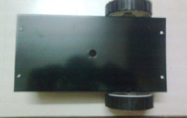
[[wysiwyg_imageupload:13665:]] 1. Mechanical 1.1 TABLE NAME OF COMPONENT QUANTITY 1. IRON CHESSY 1 PCS. 2.METAL GEARED MOTORS 2 PCS. 3.PLASTIC TYRES 2 PCS. 4. CASTER WHEEL 1PCS. 5.NUT & BOLT 3 PCS. 1.2 Structure…
AT89S51/52 ISP Programmer – Lock Bits Setting

Lock bits are set of bits to enable or disable some special security features of a microcontroller. For example, in some cases you might want to disable the memory read functionality of the microcontroller, so that the code you have written cannot be stolen by others. The number of lock bits and their functionality is…
AT89S51/52 ISP Programmer – Memory Write

This tutorial explains how to write the content in the microcontroller’s flash memory. The source microcontroller writes some values in the memory of the target microcontroller. The values that have been written can be checked by reading the buffer of the target microcontroller using a programmer. The values are nothing but the machine language instruction…