Timers are used in many different applications for example in Industrial Applications, to switch ON or switch OFF any device or a machine load for a specific period of time. In the same way the timers are used in Domestic Appliances like in Air Conditioners, Microwave Ovens, Washing Machines, Food Processors etc. The applications for the timers could also be seen in Military Applications and Space Applications, to trigger any Bomb or a Missile or to ignite booster rockets for lift offs at a specific time. Here the given project demonstrates the fully featured and customized timer built using AVR Microcontroller ATMega32.
DIY – Waveform Generator using AVR Microcontroller
To interface 8-bit DAC with AVR microcontroller ATMega32 and generate different waveforms like Square Wave, Sine Wave, Triangular Wave, Staircase Wave and Saw-tooth Wave. To generate different Analog waveforms using AVR microcontroller it is required to interface a DAC that will convert the Digital inputs given by microcontroller into corresponding Analog outputs and thus it generates different analog waveforms. The DAC output is current equivalent of digital input. So to convert it in to voltage a current to voltage converter is required.
Audio Tone Generator using AVR Microcontroller
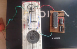
The circuit presented here demonstrates how to generate Audible Frequency from an AVR Microcontroller. The output of Microcontroller is always digital so to generate audible sound at the outset first it needs to be converted into Analog. A DAC (Digital to Analog Converter) is used for this purpose. Microcontroller generates sine wave of Audible Frequency using DAC. This sine wave is further given to Audio Amplifier that drives speaker. Microcontroller generates sine wave of fix frequency continuously. So we can hear an audible tone of fix frequency
DC Motor Control with Joystick & AVR Microcontroller
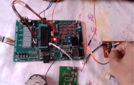
In many of the applications it is required to alter the direction of DC motor instantly. Like in washing machine, mixer, drilling machine winding – rewinding machine etc. Changing the direction of DC motor using joystick is most suitable and handy method.In industries the joystick control is most preferable way to control machinery that is operated with DC motor. The best example is 3 axis or 2 axis DC motor operated crane. In this, 3 (or 2) DC motors moves crane up or down, rotate it left or right using 3 (or 2) joysticks
How to Interface a GSM (SIM 300) Modem with ATmega32 to Send and Receive SMS- (Part 42/46)
GSM stands for Global System for Mobile Communications. It is a standard set developed by the European Telecommunications Standards Institute (ETSI) to describe protocols for second generation (2G) digital cellular networks used by mobile phones. A Modem is a device which modulates and demodulates signals as required to meet the communication requirements .It modulates an analog carrier signal to encode digital information, and also demodulates such a carrier signal to decode the transmitted information. A GSM Modem is a device that modulates and demodulates the GSM signals and in this particular case 2G signals. The modem we are using is SIMCOM SIM300. It is a Tri-band GSM/GPRS Modem as it can detect and operate at three frequencies (EGSM 900 MHz, DCS 1800 MHz and PCS1900 Mhz). Default operating frequencies are EGSM 900MHz and DCS 1800MHz.Sim300 is a widely used in many projects and hence many variants of development boards for this have been developed.
Switch Status & LED with AVR microcontroller- (Part 6/46)
Generally we know about interfacing button switches, LED with Atmega32 microcontroller. We know that interface switch’s to one port, LED’s to another port and if we press any switch the corresponding LED will glow. But all the LED’s operate with single switch we don’t know. Here we are developing the program for operating 7 LED’s with one switch. The circuit connections and programming is so simple. We will discuss here about that. First we see the circuit connections. Let us take any one port of Atemga32 controller is PortD. Connect 7 LED’s to PortD and connect on switch to remaining pin of the PortD. Now let us start the coding for microcontroller. First open the Atmel Studio software of any version. Create a new project with your desired file name. Here I am taking the project name as “button switch”.
AVR ATmega16/32 Fuse Bits
Summary Updating with the era of technology, the new microcontrollers are coming with lots of inbuilt peripherals and features. These inbuilt peripherals and features not only reduce the cost of additional circuits to be used with the controller but also provide an ease to interface additional devices (such as Modems etc) directly with the microcontroller. The…
AVR ATmega32 TWI Registers
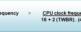
AVR (ATmega32) contains some in-built registers for TWI communication which not only reduce the level of complexity but also make the whole communication process smooth. These registers have been explained in this tutorial. 1. TWBR (TWI Bit Rate Register) : TWBR7 TWBR6 TWBR5 TWBR4 TWBR3 TWBR2 TWBR1 TWBR0 This register is used in master…
How to use I2C / TWI (Two Wire Interface) in AVR ATmega32- (Part 36/46)
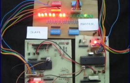
This article explores the TWI interfacing between two ATmega32 controllers. Readers are advised to go through TWI Communication and TWI registers[[wysiwyg_imageupload::]]of ATmega32 before going further. Generally modes 1 & 3 and modes 2 & 4 are used together. This article explains the use of these four modes by an experiment.To establish the communication between two ATmega32 using TWI interface. First the Master starts by sending data then the slave transmits complement of the received data to the master. When the Master receives the complemented data, it shifts the original data to left. This process of transmitting and receiving continues. As the data value reaches 0x80 the whole process is repeated. At the starting, value of the original data is 0x01. The received value is displayed on PORTB at both the ends.
Stepper Motor Angle Control using AVR Microcontroller
This project demonstrates how any device or object can be positioned to desired angle. The circuit presented here demonstrates how to position Stepper Motor at a specific Angle using AVR microcontroller. The desired Angle Position is entered by user and when He presses the button to rotate motor, the motor starts rotating and rotates till it reaches that angle. The angle can be entered in step of 15o between 0o to 360o. User can increment or decrement angle value in step of 15o and set the desire angle. Based on set angle motor rotates forward (CCW) or reverse (CW). Like if current motor angle is 60o and user enters 90o then motor rotates CCW and if user enters 30o motor rotates CW.


