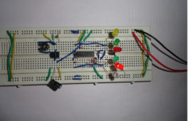
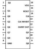
The circuit is used for decoration purpose or as an indicator. Flashing or dancing speed of LED’s can be varied with the help of variable resistor and various dancing pattern of light can be formed by slight change in the circuit. In this circuit 6 LED’s moves in one direction then again flow the opposite direction than previous. The circuit is based on two IC’s namely NE555 and CD4017 with few more components. 555 timer IC wired as an astable oscillator. In this circuit NE555 astable generates a clock for the circuit which provide a oscillating wave to the output pin 3 of IC1. You can vary the speed of oscillation with the help of VR1. The frequency of oscillation of 555 timer can be calculated by f=1.44/(R1+2*(VR1)*C1) and CD4017 is a CMOS counter/ divider IC. It take clock signal from the clock input and turn on the 10 output in sequence, each time when it receives clock input pulses. It is the most popular IC and extremely useful in various project like Light Chaser, Matrix Die. In order to understand the working of IC one must know about its individual pin.
Remote Controlled Toy Car
Remote control toy car circuit can be used to on and off the motor of the toy car with the help of your remote. You can use any remote of TV, AC, DVD player to control the movement of motors.This low cost circuit is based on the CD4017 counter IC which receives trigger pulse from IR sensor and switch ON the relay. And with the relay, motors are connected which also get switched ON. Upon receiving the second pulse motor gets turned OFF.You can control your toy car upto 5 meters range. This is a simple circuit based on infrared sensor IC TSOP1738. TSOP1738 contains photo detector and preamplifier in one package. It is three terminal device having pin 1 configured for ground, pin 2 for power supply and pin 3 as output. Keep on reading to find out how the circuit works.
LED Based Pendulum Circuit
The circuit is based on two IC’s namely NE555 and CD4017 with few more components. where 555 timer IC is wired as an astable oscillator. CD4017 is a CMOScounter/ divider IC which takes clock signal from the clock input and turns on the10 output in sequence, each time when it receives clock input pulses. It is the most popular IC and is extremely useful in various project like Light Chaser, Matrix Die.The circuit is based on two IC’s namely NE555 and CD4017 with few more components. where 555 timer IC is wired as an astable oscillator. CD4017 is a CMOS counter/ divider IC which takes clock signal from the clock input and turns on the10 output in sequence, each time when it receives clock input pulses. It is the most popular IC and is extremely useful in various project like Light Chaser, Matrix Die.
Toggle switch using CD4017
This circuit will help you to control two devices with the help of a switch. If you “on” the first device then second device remain “off”, and if you “on” the second [[wysiwyg_imageupload::]]device the first device will become “off”. Therefore you can control both the devices with the help of single switch. The circuit is built around CD4017 which is a CMOS decade counter/ Divider. Used in many applications like binary counter/decoder, frequency division, divide by N counting, Alarm system etc. CD4017 is a 16 pin IC which includes 3 input- Clock, Reset and Clock inhibit. And 10 output Q0- Q9. Pin 16 is for power supply and pin 8 is used for ground. Read more to find out working of the circuit.
Random Number Generator Using 7 Segment Display
It is very simple and easy to construct project which will display random numbers from 0 to 7 on a 7 segment display. This circuit can serve as an alternative that can be used to replace the traditional dice while playing games such as snake ladder, monopoly etc. It uses NE555 which is a well known multivibrator IC. Here 555 timer IC is wired as an astable oscillator which provide a clock pulse to CD4017 IC.CD4017 which is a medium speed Johnson Counter that works at 10MHz and has 10 decoded outputs. CD4017 ICs are widely used in frequency dividers, binary counters, divide by N counters and register design applications and CD4511 which is a BCD to 7 segment decoder.
Bi Color LED
This circuit uses Bi-color LED which creates an eye-catching running display effect. This project can be used in the places like borders of animation, pictures, [[wysiwyg_imageupload::]]short word display etc. The bi-color LEDs are similar to uni-color with the difference that there are two LEDs housed in a package. Bi-colour LEDs may have two or three leads depending upon the internal connections. In this circuit five Bi-color LEDs are used. The LEDs first light in green color, from top to bottom and then in red color, from bottom to top. The IC1 provide clock pulses to the input of decade counter IC2. At each clock pulse, IC2 counts from 0 to 9. The first five pulses lights up in green color when they reach the green anodes of the bi-color LED. Similarly, next five pulses lights up in red color when they reach the red color anodes.


