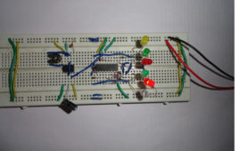
The circuit is used for decoration purpose or as an indicator. Flashing or dancing speed of LED’s can be varied with the help of variable resistor and various dancing pattern of light can be formed by slight change in the circuit. In this circuit 6 LED’s moves in one direction then again flow the opposite direction than previous. The circuit is based on two IC’s namely NE555 and CD4017 with few more components. 555 timer IC wired as an astable oscillator. In this circuit NE555 astable generates a clock for the circuit which provide a oscillating wave to the output pin 3 of IC1. You can vary the speed of oscillation with the help of VR1. The frequency of oscillation of 555 timer can be calculated by f=1.44/(R1+2*(VR1)*C1) and CD4017 is a CMOS counter/ divider IC. It take clock signal from the clock input and turn on the 10 output in sequence, each time when it receives clock input pulses. It is the most popular IC and extremely useful in various project like Light Chaser, Matrix Die. In order to understand the working of IC one must know about its individual pin.

