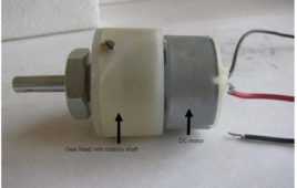
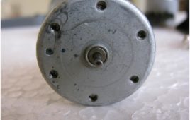
Geared DC motors can be simply put as an extension of DC Motor. The speed of the motor is counted in terms of rotation of the shaft per minute and is termed as RPM .Simple DC motors are restricted in terms of power and lack proper speed control. They can even run at speeds approximately close to 3,000 RPM which might get beyond the desired requirements of the user. However, using a geared motor can reduce down the RPM such as 150 and lower, hence providing more torque to the machine. This concept where gears reduce the speed of the vehicle but increase its torque is known as gear reduction. This Insight will explain those major as well as minor details that make the gear head and hence the geared DC motor work.
Insight – How DC Motor Works
DC Motors convert electrical energy (voltage or power source) to mechanical energy (produce rotational motion). They run on direct current. The DC motor works on the principle of Lorentz force which states that when a wire carrying current is placed in a region having magnetic field, than the wire experiences a force. This Lorentz force provides a torque to the coil to rotate.When we pass the input DC current to the coil through the brushes, it directly goes to the coil inside the motor body. This makes coil to work as an electromagnet. Magnetic fields of both magnets interact with each other that results in a force which in turn produces the necessary torque required to move the coil.
Wireless motor control through RF
Wireless remote controlled toy cars work on the concept explained in this project. Motor control through RF communication is a very interesting application and [[wysiwyg_imageupload::]]is widely used in robotics, electronics toys, automation systems etc. This topic covers the way DC motors can be driven by using the controls from a distant place. The controls are transferred from one end to another by employing an RF module. The parallel signals generated at transmission end are first encoded (into serial format) by HT12E and then transferred through RF transmitter (434 MHz) at a baud rate of around 1-10 kbps. The same signals are acquired by RF receiver after which it is decoded by HT12D. For more details, refer RF remote control.
DC Motor Controller
DC Motors are widely used for motion control in manufacturing industries. Motion of DC motor is controlled using DC Drive. DC drive changes the speed and direction of a motor. Many of the DC drives provides programmable facilities means to program the motion of motor. So here I am giving one such example where one can…
Speed Control of DC Motor
It is a simple circuit with the help of which you can control the speed of DC motor. You can also use it control the speed of windscreen wipers used in automobiles or it can be used in toys. Easy to install because of less components used and works well on wide range of power supply from 5V to 12V. This circuit is based on single IC that is NE555 which work as a-stable multi-vibrator. In this mode 555 timer is not stable and its output is continuously changes from low to high or from high to low. This continuous change from one state to another (high to low and then back to original state) produces a continuous square wave output.
Remote DC Motor controller with Digital Display
This is bit little extension to previous 89C51 based DC motor controller. A digital speed indicator (seven segment displays) are connected to show speed variation. All other things remains same NOT gates, DC driver etc. Operation of 89C51 also changes as it will now work as serial data receiver. I suggest you if you do…
Wireless DC Motor controller
In this project computer controls DC motor wirelessly through it’s LPT port. Computer generates signals that are transmitter by transmitter. These signals are received by DC motor controlling unit and it controls the operation of DC motor. 89C51 is used at receiver side which detects the signal and controls the operation of motor. IR interface…
Simple DC Motor Controller using 555 Timer IC
Controller is actually a combination of two circuits – driver circuit and Switching circuit. Driver is the actual circuit that drives DC motor and switching circuit decides how DC motor should be driven. So actually, switching circuit is the main circuit that controls the motor. Now there are two parameters of DC motor that can be controlled Speed and Direction.Changing the direction of DC motor is very simple just reverse the supply given to DC motor. For varying speed of motor you have to vary the applied DC voltage. One well known method widely used in industries is Pulse Width Modulated (PWM) speed control of DC motor also known as chopper control.
DC Motor Control using C++
This is a demo program written in C++ so that you can know how computer is used to take control action on DC Motor. Total motion control of DC motor is given here (speed control as well as direction change). Also total GUI (Graphical User Interface) is provided (buttons, mouse interface etc.). Program controls motion of motor…
DC Motor Control using PWM with ADC
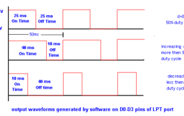
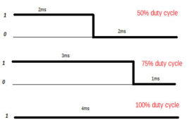
This project involves a combination of PWM (pulse width modulation) and ADC (Analog-Digital converter) to drive a DC motor at various speeds and in both clock and anti directions.PWM is a concept with which one can modify the pulse voltage varying it from 0% duty cycle to 100%.Duty cycle represents the time for which pulse is high when compared to the full pulse length.

