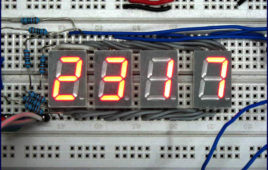
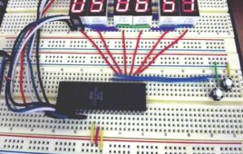
Digital clock are widely used nowadays. The usual method for programming the clock as we have all seen is the ‘SOFTWARE DELAY’ or ‘POLLING’ method generated by using looping statements such as FOR and WHILE loop. But the major drawback with this type of program is that the delay of the other instructions goes on summing every time resulting in elongated delay than required. Thus after a handful amount of time, it seems as if the Clock has slowed down. To overcome this we will use Timer with interrupt to generate delay.This project is basically divided into three parts: Controller, LCD and Keypad. The 16×2 LCD has inbuilt Hitachi’s HD44780 controller to process the data and the Keypad is configured in (4×1) fashion. This means the 4 keys are connected to four different pins having a common ground. More-over, 1 second delay is achieved by using TIMER-1 Interrupt of ATmega16.
Digital Clock with Alarm using Timer/Counter
This entire project is divided in to 2 parts, the first part demonstrates the software implementation of the digital clock on Atmega16 and the second part demonstrates the hardware implementation of digital clock on WSN-EK development kit (ATMEGA324PA). In this project we have implemented a digital clock with the help of 16 bit timer. Thus this project illustrates the basic use of timer and its interrupts. The timer will interrupt Microcontroller after every 1s and perform the given ISR (Interrupt Service Routine).
Digital Clock without Microcontroller
Digital clocks normally function by microcontrollers. Here is a circuit for electronic enthusiasts who can make a digital clock without using any expensive controllers, or having no knowledge of microcontrollers or programming. The whole functioning is solely based on simple IC’s. Components used IC 555 (Timer) — one. CD4518 (CMOS dual up counter) — two.…
Digital Clock with time set option using seven segment and 8051 microcontroller
This digital clock not only displays time (on four seven segment displays) but also provides the user an option to set the time. For this the user has to first press [[wysiwyg_imageupload::]]the reset switch after which he/she can select and set a particular digit by incrementing its value. To run the clock with the set time, the user needs to press the start button. The seven segment and switches are interfaced with microcontroller AT89C51. This idea to provide option for setting time can be implemented in conjunction with the digital clock circuit. The control options for time setting are provided by means of tactile switches which are made active low. This circuit uses four such switches. As soon as S1 is pressed, the running clock stops and it goes into the reset mode where the first segment is activated. The segment to be set can be selected in cyclic order each time S2 is pressed. After selecting the desired segment, its value can be changed by using S3.
Simple Digital clock using 8051 microcontroller (AT89C51)
A digital clock is one that displays time digitally. The circuit explained here displays time with two ‘minutes’ digits and two ‘seconds’ digits on four seven [[wysiwyg_imageupload::]]segment displays. The seven segment and switches are interfaced with 8051 microcontroller AT89C51. This circuit can be used in cars, houses, offices etc. As soon as the Vcc supply is provided to this circuit, the clock starts from 00:00. The time is displayed on four seven segments (in common anode configuration) by using the concept of multiplexing. This is achieved by using timer interrupt (Timer0) of AT89C51 which is configured to refresh seven segments. The segments are refreshed many times in a second for simultaneous display. The clock runs with a delay of exactly one second. Timer1 has been used to produce a time delay of one second. The data pins (a–h) of all the segments are interconnected and receive signal from port P2 of the microcontroller. The control or enable pins (common anode) are connected to pins 1-4 of port P1 (P1^0 – P1^3).
Digital Clock using Seven Segment Display and ATMega16
In this ATMega16 AVR project we will be designing and implementing a digital clock with the aid of a atmel AVR ATMega16 microcontroller and seven segment display.As such before going through this digital clock AVR project it is recommended to complete the tutorial on Interfacing a Seven Segment Display with the AVR Microcontroller.Although this AVR project was designed around the ATMega16 the project could have utilized another microcontroller such as an ATMega32, ATMega8515, etc.


