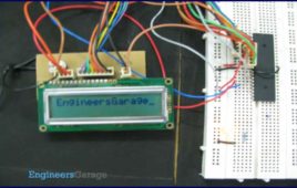
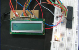
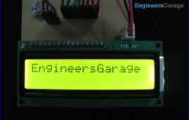
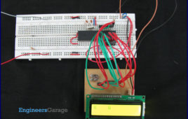
This article presents an interesting approach for sound activated display system. This system displays two different messages for odd and even number of [[wysiwyg_imageupload::]]sounds. When the sound is produced for the first time the first message is displayed on the LCD. At the second sound, a second message is displayed. The first message reappears at the third sound. Thus alternate messages are displayed every time a sound, say clap, is detected by the system. The project is build around the 8051 microcontroller (AT89C51) along with LCD and a condenser microphone.The circuit consists of four major modules, namely, a sound sensor, an amplifying circuit, a control circuit and a display module. A switching circuit is also employed after the amplifier. Any sound, say clap, is detected by a microphone (condenser mic) which acts as the sound sensor. This mic is connected to a two stage transistor amplifier. The mic output is thus amplified to a suitable level so that it can be detected at the TTL logic.
Sound operated display on LCD using 8051 microcontroller
This is an interesting idea in which a message is displayed on an LCD screen whenever a sound is produced. The message remains on LCD for a short duration of [[wysiwyg_imageupload::]]time and then disappears. This topic demonstrates the interfacing of a sound operated circuit and LCD display with the 8051 microcontroller (AT89C51). The circuit can be used to display welcome message at entrance; or warning messages at public places. It can also be used to aid communication for deaf and dumb people.The circuit consists of four major modules, namely, a sound sensor, an amplifying circuit, a control circuit and a display module. A switching circuit is also employed after the amplifier.Any sound, say clap, is detected by a microphone (condenser mic) which acts as the sound sensor. This mic is connected to a two stage transistor amplifier. The mic output is thus amplified to a suitable level so that it can be detected at the TTL logic.
Celsius and Fahrenheit scale digital thermometer using 8051 microcontroller (AT89C51)
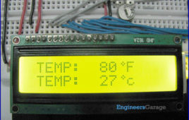
Fahrenheit scale digital thermometer is a temperature indicator which displays temperature in Fahrenheit scale. It is similar to Celsius scale digital thermometer, [[wysiwyg_imageupload::]]except a little modification in the microcontroller program. The temperature sensed in Celsius scale in the Celsius scale thermometer project is converted into the Fahrenheit scale temperature just by using the Celsius to Fahrenheit conversion formulae. This project also uses 8051 microcontroller (AT89C51).A digital thermometer can be easily made by interfacing a temperature sensor to the microcontroller AT89C51. The temperature sensor used in the project isLM35. The LM 35 IC generates a 10mV variation to its output voltage for every degree Celsius change in temperature. The Output of the temperature sensor is analog in nature so we need an analog to digital convertor for converting the analog input to its equivalent binary output. The ADC 0804 is the analog to digital convertor IC used in the project. 0804 is a single channel convertor which converts the analog input up to a range of 5V to an equivalent 8-bit binary output.
Celsius scale digital thermometer using 8051 microcontroller (AT89C51)
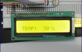
Celsius scale thermometer displays the ambient temperature through a LCD display. It consists of two sections. One is that which senses the temperature. This is a temperature sensor LM 35. The other section converts the temperature value into a suitable number in Celsius scale which is done by the ADC0804. A digital thermometer can be easily made by interfacing…
How to display text on 16×2 LCD using 8051 microcontroller (AT89C51)- (Part 7/45)
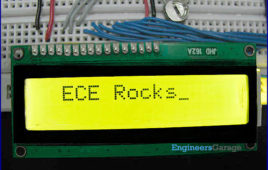
Several electronic devices and projects require a message to be displayed in order to indicate their functioning. This topic explains how to display a message [[wysiwyg_imageupload::]](string) on 16×2 LCD by interfacing it to 8051 microcontroller (AT89C51). A single character can be displayed on LCD by properly configuring its data and command registers. A string is nothing but a sequential arrangement of several characters that can be displayed on LCD by using the following algorithm. Here P2 port of the microcontroller is used as output port which sends the data byte to data pins of the LCD. Read more to find out how LCD is interfaced with the microcontroller and how does the circuit work.
Automatic bidirectional visitor counter using 8051 microcontroller (AT89C51)

A counter that can change its state in either direction, under control of an up–down selector input, is known as an up–down counter. The circuit given here can [[wysiwyg_imageupload::]]count numbers from 0 to 9999 in up and down modes depending upon the state of the selector. It can be used to count the number of persons entering a hall in the up mode at entrance gate. In the down mode, it can count the number of persons leaving the hall by decrementing the count at exit gate. It can also be used at gates of parking areas and other public places.This circuit divided in three parts: sensor, controller and counter display. The sensor would observe an interruption and provide an input to the controller which would run the counter in up/down mode depending upon the selector setting. The same count is displayed on a set of 7-segment displays through the controller. Read more to find out about working of the circuit and how microcontroller is coded.
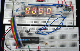
Alarm Clock using 7-Segment Display and 8051 microcontroller (AT89C51)
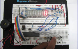
An alarm clock is a clock that indicates a pre-set time by producing sound at that time. This functionality of digital clock is used to awaken people or remind them [[wysiwyg_imageupload::]]of something. This circuit is an extension to the digital clock with time setting option. Here an extra switch is provided to set the alarm. While the alarm is set, the clock time does not stop and runs in the background. The project is built around the 8051 microcontroller (AT89C51). The option to set alarm is provided by providing an extra switch S5, with the microcontoller At89C51, which is made active low.Whenever S5 is pressed, the time display goes off and only 1st segment is activated. But the clock time still runs in the background. In this mode, a segment can be selected in cyclic order by pressing S2. After selecting the desired segment, its value can be changed by using S3. Once the digits and hence the alarm is set, S4 is pressed to start the clock again. As soon as the set alarm time is reached, a buzzer gets signal from the microcontroller thus producing sound.
Digital Clock with time set option using seven segment and 8051 microcontroller

This digital clock not only displays time (on four seven segment displays) but also provides the user an option to set the time. For this the user has to first press [[wysiwyg_imageupload::]]the reset switch after which he/she can select and set a particular digit by incrementing its value. To run the clock with the set time, the user needs to press the start button. The seven segment and switches are interfaced with microcontroller AT89C51. This idea to provide option for setting time can be implemented in conjunction with the digital clock circuit. The control options for time setting are provided by means of tactile switches which are made active low. This circuit uses four such switches. As soon as S1 is pressed, the running clock stops and it goes into the reset mode where the first segment is activated. The segment to be set can be selected in cyclic order each time S2 is pressed. After selecting the desired segment, its value can be changed by using S3.
Seven segment multiplexing using 8051 microcontroller (AT89C51)- (Part 4/45)
Many electronic devices use four seven segment displays to display their output. The four seven segment displays can be connected in two ways. One way is to [[wysiwyg_imageupload::]]connect the four displays to the four ports of the microcontroller. However this is not a good way, as this will block all the ports and we cannot use microcontroller for any other purpose.To overcome this problem, we use multiplexing of seven segment display. In multiplexing we use the concept of persistence of vision i.e., human brain cannot differentiate between two events occurring at a time difference of less than .04 sec. In this case the four digits are displayed one after the other so fast that the human brain cannot detect the difference. Although only one digit is displayed at a time it appears as a four digit number.The circuit presented here demonstrates the above principle in form of a counter which counts from 0 to 9999 with a small delay.
Digital dice using 8051 microcontroller (AT89C51)
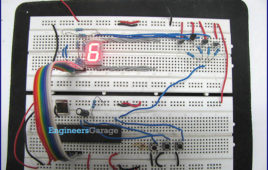
All of us have played the game of gambling and are well aware of the working of the dice. Here we are presenting a circuit to make a electronic digital dice with the [[wysiwyg_imageupload::]]help of a seven segment controlled by an 8051 microcontroller. We have already gone through the seven segment circuit interfacing (refer ‘interfacing seven segment’ section). The circuit can be divided into two units: the microcontroller unit and the seven segment unit. The microcontroller unit contains a microcontroller circuit (for microcontroller circuit details, refer ‘led blinking’ section) and the seven segment unit contains a seven segment circuit which is interfaced to the controller (for more details of seven segment circuit, refer ‘seven segment interfacing’ section). This circuit displays the numbers from 1 to 6 continuously and it halts at the position user wants and starts again from the same position with the next instruction of the user.
User input based seven segment display using 8051 microcontroller (AT89C51)- (Part 3/45)
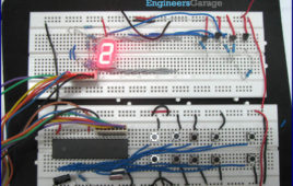
This article is a simple application built around the seven segment display. The circuit has ten inputs corresponding to digits zero to nine. Whenever an input is pressed the corresponding digit is displayed on the seven segment.The microcontroller used is AT89C51 which belongs to the 8051 series of microcontroller.The circuit can be divided into two units: the controller unit and the display unit. The controller unit consists of a microcontroller circuit. The microcontroller used here is AT89C51 . The display unit consists of a seven segment circuit which is interfaced to the microcontroller. The circuit is similar to the seven segment circuit with the only difference that here we have ten input pins. Each input pin corresponds to one of the digits to be displayed on the seven segment. Here the pin 0 to pin 7 of port P3, pin 6 and pin 7 of port P 1 are made the input pins. The output is sent to the seven segment through Port 2 of the microcontroller.
How to interface seven segment display with 8051 microcontroller (AT89C51)- (Part 2/45)

Seven Segment displays are used in a number of systems to display the numeric information. The seven segment can display one digit at a time. Thus the no. of [[wysiwyg_imageupload::]]segments used depends on the no. of digits in the number to be displayed. Interfacing seven segment with a controller or MCU is tricky. This article explains the interfacing of seven segment with MCU AT89C51. It displays the digits 0 to 9 continuously at a predefined time delay. Seven Segment are available in two configuration – (1) Common Anode (2) Common Cathode.Here common anode seven segment display is used because the output current of the microcontroller is not sufficient enough to drive the LED’s, similar to the case of driving an LED. The circuit diagram shows the connections of seven segment to the controller. The pins a to g of the Seven Segment are connected to the Port P2 of the microcontroller. The common pin of the seven segment is connected to Vcc. The ‘h’ has not been used, which is the dot pin of the controller.
How to interface LEDs with 8051 microcontroller (AT89C51)- (Part 1/45)

This article introduces you to the very basic operation of taking an output from the microcontroller AT89C51. It demonstrates the principle behind interfacing LEDs [[wysiwyg_imageupload::]]with 8051 microcontroller. Here we have demonstrated the aforesaid principles by blinking LEDs continuously i.e., switching them on and off.AT89C51, which belongs to the family of 8051 series of microcontrollers, is very commonly used by a large community of hobbyist and engineers. Its simplicity and ease of programming with inbuilt features easily makes its position in the top preferred list of microcontroller for both beginners and advanced user. LEDs need approximately 10mA current to flow through them in order to glow at maximum intensity. However the output of the controller is not sufficient enough to drive the LEDs, so if the positive leg of the LED is connected to the pin and the negative to ground as shown in the figure, the LED will not glow at full illumination.
How to interface LCD in 4 bit mode with AVR microcontroller- (Part 10/46)
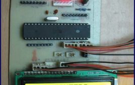
This article explains interfacing of LCD with ATmega16 using 4-bit mode. In this mode only four pins are used for sending data and command instructions. This [[wysiwyg_imageupload::]]mode has the advantage over the 8-bit mode as it uses less number of pins. The remaining pins of the controller are available for normal use. The Data or command is sent in nibble form (1 nibble= 4 bit) in the 4-bit mode. The higher nibble is sent first followed by the lower nibble. The function of RS, RW and EN pins remains similar to 8-bit mode. The LCD can be configured in 4-bit mode by sending appropriate instruction which is called “Function set” to it. The Function set is hexadecimal instruction for LCD MPU unit, which selects working modes of LCD. Continue reading to find out LCD can be interfaced with simple programming and circuitry.
Display custom characters on LCD using AVR Microcontroller (ATmega16)- (Part 9/46)

This is the most interesting article to play with LCD. After going through the article, you can create any character/symbol which cannot be created using the [[wysiwyg_imageupload::]]ASCII values for example smiley. You can even create small games. Conventionally 16X2 LCD is use to display text or numerical values. It is possible to display special characters, your own designed characters too on LCD by using its 5 x 8 matrix block. These special characters are stored in the CGRAM of LCD. This article shows how to create and display special character on LCD using ATmega16. For more details refer to the article how to create custom characters. This article assumes that the readers are aware of the concepts of interfacing LCD with AVR microcontroller (ATMEGA 16). For more information about interfacing LCD with AVR, refer How to display string on LCD using AVR. In order to create a custom character its configuration is first defined in the CGRAM of the LCD. A maximum of eight characters can be stored at a time in the 16 x 2 LCD.
How to display text on 16×2 LCD using AVR microcontroller (ATmega16)- (Part 8/46)
This article is in continuation to the article Single character LCD display using AVR. The aforesaid article shows how to display a single letter on LCD. Moving [[wysiwyg_imageupload::]]forward towards learning to work with LCD, this article explains how to display a string on LCD. Displaying string is occasionally used in many applications. The connection of the LCD with the AVR microcontroller (ATmega16) is shown in the circuit diagram. A string is nothing but a sequence of characters. The following steps explain how to display a string on the LCD. Keep on reading to find out How to code and interface in order to display text on 16×2 LCD using AVR microcontroller (ATmega16).
How to interface 16×2 LCD with AVR microcontroller (ATmega16)- (Part 7/46)
LCD is used to present textual information to the users. It is great fun to work with LCD. Also LCD makes your application more interactive. LCD comes in various [[wysiwyg_imageupload::]]configurations and the most popular one is 16×2 matrix display. This article shows the interfacing of ATmega16 with LCD by displaying a simple character on the LCD. For more information about LCD, refer the article LCD interfacing. In this project LCD is working in 8-bit mode i.e., the data transferred to the LCD must be in 8-bit data form. The PortA of ATmega16 is connected to data pins of LCD and is defined as LCD_DATA. PortB is defined as control pins (Rs, R/W and En). Conceptually, interfacing LCD with AVR microcontroller is similar to that of interfacing it with any other microcontroller. Continue reading to understand interfacing circuitry and coding concepts of the project.
How to display text on 16×2 LCD using PIC18F4550 Microcontroller- (Part 6/25)
In Several automated and semi-automated devices require a message to be displayed in order to indicate their working status. In continuation to LCD interfacing [[wysiwyg_imageupload::]]with PIC18F4550, this article explains how to display a message or string on a 16×2 character LCD. In the previous article, a single character was displayed on LCD by properly configuring its data and command registers. A string is nothing but a sequential arrangement of several characters that can be displayed on LCD by using the programming steps mentioned here. The circuit connections and user-defined functions are same as earlier. The LCD data pins are connected to PortB of PIC18F4550 while the control pins are connected to first three pins. Read more to find how easily can one interface a display unit with a PIC micro controller.
How to interface LCD with PIC18F4550 Microcontroller- (Part 5/25)
For basic details and operations of character LCD, refer LCD interfacing with 8051. Here LCD has been interfaced in 8-bit mode* with data pins (D0-D7) connected to PortB of PIC18F4550. The LCD control pins RS, R/W and EN are connected to PortA pins RA0, RA1 and RA2 respectively. *Character LCD can also be interfaced…
Seven Segment Multiplexing using PIC18F4550 Microcontroller- (Part 4/25)

As explained earlier, a seven segment interfaced with PIC uses almost an entire port (minimum 7 pins) to display a value. But a real time application, like watch, [[wysiwyg_imageupload::]]calculator etc., usually requires at least 3-4 seven segments. In such a case it is not advisable to use a port of the controller for each seven segment. In these cases, multiplexing technique is used to work with more than one seven segment. Here multiplexing of four seven-segments has been explained withPIC18F4550 to display four-digit count from 0000 to 9999. The multiplexing concept is based on the principle of persistence of human vision. A human eye cannot detect a visual change if the frames change at a rate of 25 (or more) frames per sec. This means that if events occur continuously with a time difference of less than or equal to 0.04 sec (1/25 sec), then we cannot notice the transition between those events.