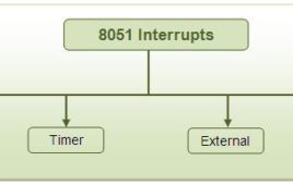
Interrupt is one of the most important and powerful concepts and features in microcontroller/processor applications. Almost all the real world and real time systems built around microcontrollers and microprocessors make use of interrupts. What is Interrupt The interrupts refer to a notification, communicated to the controller, by a hardware device or software, on…
Digital Clock Using Interrupt

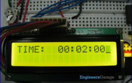
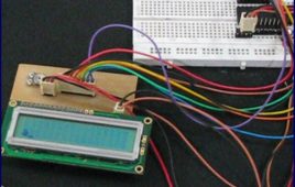
Digital clock are widely used nowadays. The usual method for programming the clock as we have all seen is the ‘SOFTWARE DELAY’ or ‘POLLING’ method generated by using looping statements such as FOR and WHILE loop. But the major drawback with this type of program is that the delay of the other instructions goes on summing every time resulting in elongated delay than required. Thus after a handful amount of time, it seems as if the Clock has slowed down. To overcome this we will use Timer with interrupt to generate delay.This project is basically divided into three parts: Controller, LCD and Keypad. The 16×2 LCD has inbuilt Hitachi’s HD44780 controller to process the data and the Keypad is configured in (4×1) fashion. This means the 4 keys are connected to four different pins having a common ground. More-over, 1 second delay is achieved by using TIMER-1 Interrupt of ATmega16.
How To Interrupt The Arduino Board Periodically- (Part 26/49)
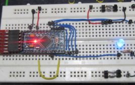
The interrupt is a method by which a microcontroller is made to divert from current path of code execution to do some other important things that needs immediate processing. The code which is written to process whenever an interrupt occurs is called an Interrupt Service Routine (ISR). Once an interrupt occurs the controller stops its current processing and start executing the ISR and returns back to the previous task once it finish the ISR. This particular project explains how to make a variable frequency generator with the help of Arduino.The Arduino is referred to as an easy prototyping platform which has been popular among both hobbyist and experts and widely used in industries as well. Any AVR microcontroller based board which follows the standard Arduino schematic and is flashed with the Arduino bootloader can be called an Arduino board.
Interfacing ADC0808 with Serial port (RS232) using interrupt clock from 8051 microcontroller (AT89C51)- (Part 27/45)
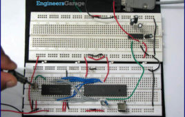
In many applications data collected from multiple sensors is transmitted to PC for display or further analysis. The conversion of data from analog to digital form is done using an ADC. The digital data from the ADC is transferred to the computer using serial port. This circuit demonstrates the principle and operation of interfacing an ADC0808 with serial port of PC using the microcontroller AT89C51. The circuit is divided into three parts: ADC, controller and serial port. This circuit can be used as an intermediate circuit in many applications.ADC0808 which is an 8-bit resolution ADC has eight input channels i.e., it can take a maximum of eight analog inputs. The circuit uses the first analog input pin to take the analog input signals from the preset. To provide clock input to the ADC, Timer0 is used in interrupt enabled mode to generate a clock of frequency 500 KHz. To enable the Timer0 in interrupt enable mode, the register IE is loaded with the value 0x82. Every time the timer completes the counting, pin P1.2 toggles its state.
Interfacing RFID with 8051 microcontroller (AT89C51) using serial interrupt- (Part 35/45)
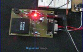
This topic covers the interfacing of RFID system with microcontroller through serial interrupt. An RFID system consists of a reader device and a transponder. A transponder or tag has a unique serial number which is identified by the reader. RFID tag is applied to products, individuals or animals to identify and track them through this number. The interfacing has been…
8051 and 8051 Microcontroller

Intel Corporation fabricated the 8 – bit microcontroller which was referred as MCS-51 in 1981. This microcontroller was also referred as “system on a chip” because it has 128 bytes of RAM, 4Kbytes of ROM, 2 Timers, 1 Serial port, and four ports on a single chip. The CPU can work for only 8bits of data at a time because 8051 is an 8-bit processor.8051 microcontrollers use two different kinds of memory such as UV- EPROM, Flash and NV-RAM. Hence 8051 will not be seen in the part number even though it is the most popular member of the 8051 family. Atmel fabricated the flash ROM version of 8051 which is popularly known as AT89C51 (‘C’ in the part number indicates CMOS). The flash memory can erase the contents within seconds which is best for fast growth.
RTC DS12C887 Interrupts
RTC DS12C887 has three interrupts, namely, Alarm interrupt, Periodic interrupt & Update interrupt. ALARM INTERRUPT The alarm interrupt occurs whenever the current time matches the alarm time. When this interrupt occurs, the corresponding flag in the Register C is set. The IRQ pin also goes low only in case the alarm interrupt enable bit…
Digital clock using RTC DS12C887 and 8051 microcontroller (AT89C51) using update interrupt
This article is an improved variant of Digital clock using RTC DS12C887 and 8051 with time set. In the earlier article, we discussed the basics of extracting data from [[wysiwyg_imageupload::]]the RTC DS12C887 using the 8051 microcontroller (AT89C51). This article is in continuation to the above article and introduces you to the concept of handling interrupts for extracting time and other information from the RTC.Interrupts offer a great flexibility to handle RTC. Interrupts have several advantages over the method of polling as discussed in the previous article. It reduces the unnecessary usage of microcontroller’s memory and processing powers, thereby keeping the processor free for other use. RTC 12C887 has three interrupts, namely, Alarm interrupt, Periodic interrupt & Update ended interrupt. For detailed information, check RTC interrupts. The free source code for the program is available in C.This article assumes that the user is aware of real time clock and the basic interfacing of DS12C887 with 8051 microcontroller (AT89C51) including the pin description, memory and registers of RTC DS 12C887.
How to interface LDR with ADC0808 using interrupt clock from 8051 microcontroller (AT89C51)- (Part 26/45)

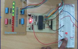
This circuit demonstrates the principle and operation of interfacing an LDR with ADC0808 using the controller AT89C51. This is an 8 channel ADC i.e., it can take [[wysiwyg_imageupload::]]eight input signals. The output is displayed on the LCD. ADC0808 is an 8-bit resolution IC with eight input pins. LDR is used to provide the analog input. The output of the LDR is displayed on a 16×2 LCD. A clock of frequency 500 KHz is generated using Timer0 in the interrupt mode. To enable the interrupt, the value of the register IE is set to 0x82.The output pins of ADC are connected to the port P0 of the AT89C51. The pin10 of the ADC is connected to pin8 (P1.7) of the controller for clock input. ALE, pin22 of the ADC is connected to pin1 (P1.0) of controller. OE, pin9 of the ADC is connected to pin4 (P1.3) of controller. SC, pin6 of the ADC is connected to pin2 (P1.1) of the controller. EOC, pin number 7 is connected to pin 3 (P1.2) of controller.
How to use External (Hardware) Interrupts of AVR Microcontroller (ATmega16)- (Part 22/46)
When an interrupt occurs, the normal flow of instructions is suspended by the microcontroller and the code corresponding to the interrupt, which has occurred, is executed. Once the code corresponding to the interrupt is executed completely the execution again begins from the same instruction where it was stopped. Following is what happens when an interrupt…
How to use internal ADC of AVR microcontroller using interrupts- (Part 28/46)
This article is in continuation to AVR interrupts. There are two types of interrupts external and internal in AVR microcontroller. The aforesaid article covers [[wysiwyg_imageupload::]]external interrupts. AVR microcontrollers have seventeen internal interrupts. These internal interrupts are generated by the internal peripherals of Microcontroller like Timer, ADC etc. The internal interrupts are used for efficient operation of the internal peripherals. This article explains the internal interrupts using the example of an ADC interrupt. Each internal peripheral system consists of one IE (interrupt Enable) bit which activates the internal interrupts of that peripheral. For example, in-built ADC of AVR consists of ADIE (ADC interrupt Enable) bit in ADCSRA register.In addition, the I-bit of SREG is also activated to activate interrupts. SREG is a status register of AVR microcontroller which contains information about the result of most recently executed arithmetic instructions.
RFID interfacing with AVR microcontroller (ATmega16) using interrupts- (Part 40/46)
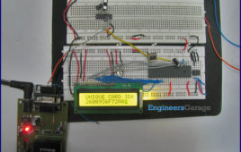
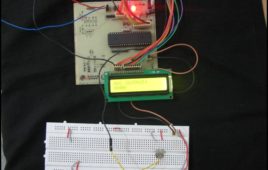
This article covers how to extract and display the twelve byte unique tag ID received by RFID module on LCD using interrupt method. Before proceeding to this [[wysiwyg_imageupload::]]article readers must have knowledge of serial interrupt and LCD. In the previous article of RFID, polling method was used where the microcontroller was continuously monitoring the RXC flag. Keeping the microcontroller busy in monitoring the flag is not a good programming technique, so instead of polling method a programmer should prefer using interrupts. Since the output data of the RFID module uses RS232 protocol and is serial in nature, serial interrupt is used to receive the twelve byte unique ID. Whenever an RFID tag comes in the proximity of the RFID reader module, the module transmits the twelve byte unique ID. Every time one byte of data is received, the controller is interrupted and the corresponding ISR gets executed, which stores the byte in a temporary variable and sends it to the LCD for display.
Serial communication with AVR microcontroller using interrupts- (Part 23/46)
In our previous articles on serial data transmission using AVR microcontroller we have demonstrated serial communication using the polling method. In Polling, [[wysiwyg_imageupload::]]the microcontroller waits for the RXC flag (in the case of serial receiver) to go high and then moves to the next instruction. This is not a good programming technique to keep the microcontroller busy to monitor the RXC flag. Alternatively, serial interrupts can be used to transmit and receive data. This increases the efficiency of the code and keeps the processor free for other tasks. The article explains serial data reception using interrupts concepts. It is recommended that the readers should study the article on AVR Interrupts before proceeding. The UCSRB register has RXCIE (Reception Complete Interrupt Enable) bit, which is used to enable the serial reception interrupt. The I-bit of SREG register is must be set to enable global interrupt of ATmega16. The circuit diagram is same as used in previous article of USART.