The LCD module makes an embedded system completely independent with which can take analog or digital input on its input pins and display the corresponding output in its own screen along with generating other kind of outputs. The LCD modules comes in different sizes varies from single line monochrome display to large graphical color display all of them using almost same method for displaying data. The Arduino can be used as a stand-alone board of which the output or inputs can be taken from the boards or given to the board. The Arduino board even though has various kinds of communication ports they can’t match with the effectiveness provided by the LCD module. Moreover the LCD module eliminates the requirement for having a PC or any other kind of devices connected with the Arduino board to display the data send by the board.
LCD Scrolling Display Module- (Part 30/46)
A microcontroller is a device which has an inbuilt processor surrounded by few dedicated hardware modules. Once the microcontroller initializes them they start operating on their own. In case of an ADC it will do the sampling and digital to analog conversion all by itself and keep the converted data in its buffer so that the microcontroller can read that later. The advantage of this kind of implementation is that the microcontroller is free to do other tasks during that time and hence increase the overall efficiency. That was the case of hardware modules or peripherals inside a microcontroller which increases the processing efficiency of the built in processor. The efficiency can increase even more if the external hardware attached to the microcontroller can also does lot more tasks by their own without depending the microcontroller.
How to Implement SPI Using PIC18F4550- (Part 24/25)
The Serial Peripheral Interface (SPI) is a high speed, synchronous, serial communication standard. This communication protocol is basically a Master – Slave implementation where the master device controls the clock based on which the slave devices operate. The master communicates with a slave or a number of slaves in a system through the SPI bus. The SPI bus requires a minimum of three wires including SDO (Serial Data Out), SDI (Serial Data Input) and SCK (Serial Clock). Since it is a master controller system the SDO is also called MOSI (Master Output Slave Input) and the SDI is also called MISO (Master Input Slave Output). The SPI is a full-duplex high speed communication protocol. The master and slave can transmit and receive data at the same time. The master is the device which generates clock for all these data transmissions. Read PIC microcontroller tutorial based on PIC18F4550 microcontrollers in which one of the microcontroller acts as a slave transmitter and the other acts as master receiver. With the help of an LCD, this particular project demonstrates the complete data transfer between a master and slave when both the master and slave are transmitting and receiving the data at the same time.
How to use PIC18F4550 as a SPI Slave Transmitter- (Part 25/25)
The Serial Peripheral Interface (SPI) is a high speed, synchronous, serial communication standard. This communication protocol is basically a Master Slaveimplementation where the master device controls the clock based on which the slave devices operates. The master can communicates with one or more slave in the system through SPI bus. The SPI bus requires a minimum of three wires i.e. a SDO (Serial Data Out), SDI (Serial Data Input) and SCK (Serial Clock). Since it is a master controller system the SDO is also called MOSI (Master Output Slave Input) and the SDI is also called MISO (Master Input Slave Output).The SPI is a full-duplex high speed communication protocol. The master and slave can transmit and receive data at the same time. The master generates clock for all these data transmissions.The SPI is special because it is simple and easy to implement in the hardware. The article explores the SPI hardware module of the PIC18F4550 microcontroller. This project will help in better understanding of the SPI protocol in detail.
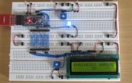
Displaying Regional Languages on LCD using Arduino
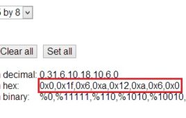
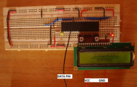
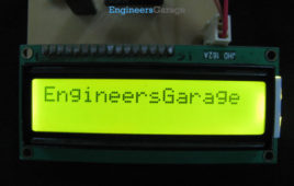
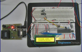
This project uses cheap Hitachi HD44780 based 16×2 LCD to display regional Indian language. These displays are designed for English text only, but they have [[wysiwyg_imageupload::]]provisions to display custom characters. On the LCD, each character is 8 pixels high by 5 pixels wide. Using a custom character designer, regional fonts were converted to hex codes, later to be used in the project. In order to understand the theory behind custom character generation we have to take a look at the memory mapping of HD44780.To display user information on regional language the characters need to be mapped onto a standard keyboard. In this case, the custom characters are mapped to a standard US-EN keyboard. When defining new character set, ASCII values of keys are assigned uniquely to each new custom character in ascending order [order is important as binary search is employed!]. Keep on reading to find out how the circuit is coded and how the connections are made.
How to create custom characters on 16×2 LCD using 8051 microcontroller (AT89C51)- (Part 10/45)
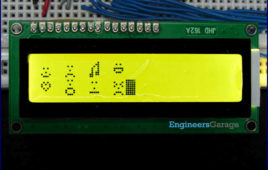
The commonly used 16×2 LCD can also display custom made characters besides numbers, alphabets & special characters. Any character can be made to appear on a 5×8 pixel matrix element without knowledge of its ASCII value. The idea explained here demonstrates the principle and operation of a simple LCD custom character display using 8051 microcontroller (AT89C51). When the ASCII code for any character, say ‘A’, is sent to be displayed on LCD module, the module’s controller looks up the appropriate 5×8-pixel pattern in ROM (read-only memory) and displays that pattern on the LCD. There are 8 symbol locations where a custom character can be stored as shown in the following right table. These locations will have a particular bitmap layout corresponding to the custom character. To display an arrow sign, the bitmap values are mapped to a base address location, say 64 (ASCII code 0).
Computer Monitors – CRT, LCD, LED, Plasma & OLED Display Monitors
A computer monitor, technically termed as visual display unit is an output device that presents the information from the CPU on the screen working as an interface between CPU and the user. A cable connects the monitor to a video adaptor or video card which is set up on the motherboard of the computer. The CPU (Central Processing Unit) sends instruction to the video adaptor telling what needs to be displayed on the screen. The video adaptor converts the instructions into a set of corresponding signals and sends to the monitor. Monitor contains a circuitry that generates the picture on the screen from the set of signals. The major parameters that measure the performance of a monitor are luminance, contrast ratio, resolution, dot pitch, response time, refresh rate and power consumption. The common problem that arises in monitors is dead pixels, blurred screen, phosphor-burn, etc.
Difference Between LCD and LED Display
LCD (Liquid Crystal Display) and LED (Light Emitting Diode) Displays are two major display technologies being widely used today. LED Displays are technological advancement of LCD displays. LED displays are the LCD displays with an LED backlight to power up the LCD panel. It means that LEDs are placed behind or around the LCD panel…
Insight – How LCD works
LCD, an acronym for Liquid Crystal Display revolutionized the modern display technology with its compactness and versatility. Today it is seen embedded in various electronic gadgets and devices like T.V., Computers, Laptops, Watches, etc. A Liquid crystal coating is the heart of the display which is sandwiched between two polarized glasses. LCD’s are available in various shapes and sizes depending on the configurations. A 16×2 LCD shown in the image below can display 32 characters with 16 characters in each row. It is capable to display any character with ASCII values ranging from 0 to 255.
How to interface 16×2 LCD in 4-bit mode with PIC Microcontroller (PIC18F4550)- (Part 7/25)
The 16×2 character LCD can work in two modes, namely, 8-bit and 4-bit. These modes basically correspond to the number of data pins used in interfacing LCD. 8-[[wysiwyg_imageupload::]]bit mode uses all the data lines and has been explained in LCD interfacing with PIC18F4550. In 4-bit mode, only four data pins of LCD are connected to the controller. This mode, thus, saves four pins of the controller unlike 8-bit mode. The configuration and display method of LCD in 4-bit mode has been explained here. The 8-bit mode of LCD interfacing with PIC has been explained earlier. In the 4-bit mode the (8-bit) data/command is sent in nibble (four bits) format to LCD. The higher nibble is sent first followed by the lower nibble. In 4-bit mode only four data pins (D4-D7) of LCD are connected to the controller. The control pins (RS, RW and EN) are connected the same way as in 8-bit mode.
How to create custom characters on 16×2 LCD using PIC18F4550- (Part 8/25)
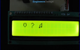
The 16×2 character LCD can also be used to display custom characters other than numerals, alphabets & special characters. Refer LCD interfacing with PIC. Some [[wysiwyg_imageupload::]]special shapes like hearts, arrows, smileys etc. can easily be displayed on the 5×8 pixel pattern of character LCD. These shapes are first stored at a special location in LCD’s controller and then displayed on the LCD module. This procedure has been explained here by using PIC18F4550. The special characters are generated by bit-mapping of LCD’s 5×8 bit pixel matrix. Refer Creating custom characters on LCD using 8051 for more details on bitmap generation and storing custom values in custom generator (CG) RAM of LCD’s controller. The mikroC IDE provides LCD Custom Character tool to create the bitmap of user defined custom character. Read further to know how are the characters created.
How to display an image on Graphics LCD using AT89C52- (Part 45/45)
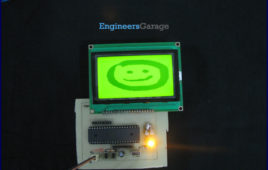
The Graphics LCD as the name suggests is a type of LCD which can display graphics. The graphical representation of any data presents good understanding thanjust characters. More user friendly applications can be designed by using the graphical LCDs. The graphical LCD can be used for advertisement boards or information boards and so on. This article explains the method of displaying image on a 128×64 graphical LCD using AT89C52. For basic operations and working, refer Graphics LCD interfacing with 8051. Microcontroller AT89C52 has been used to control the operations of the graphical LCD. The Graphics LCD used here is JHD12864E. This LCD is divided into two parts which are controlled by two different controllers. Each of these parts is divided into rows and columns. For basic instructions and programming procedure, refer to interfacing Graphics LCD with 8051. Also see displaying text on Graphics LCD. Read more to make interesting graphics on this florescent piece of display.
How to display string on Graphics LCD using 8051 Microcontroller (AT89C52)- (Part 44/45)
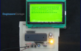
Simple operations with graphics LCD have been explained in the previous article. This article demonstrates the functionality of graphics LCD to display strings of [[wysiwyg_imageupload::]]different fonts. It explains the program to display strings in 8×8 and 5×7 fonts and also to scroll them vertically.The Graphics LCD used here is JHD12864E. This LCD is divided into two parts which are controlled by two different controllers. Each of these parts is divided into rows and columns. For basic instructions and programming procedure, refer to interfacing Graphics LCD with 8051.To display different font types, corresponding header files have been created. These header files contain the bitmap information of all alphabetic, numeric characters and symbols of a particular font. These header files are included into the main program. (The header file declarations are given in Code2).
How to interface Graphics LCD with 8051 Microcontroller (AT89C52)- (Part 43/45)
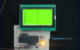
The graphical LCD used here is JHD12864E. This LCD is divided into two parts which are controlled by two different controllers. Each of these parts is divided into [[wysiwyg_imageupload::]]rows and columns.User friendly visual displays are used nowadays to keep track of working of any device. Such a visual display can be anything ranging from old Analog meters to new and smart Digital meters. In digital world to keep track of devices, LCDs are very commonly used. LCDs are easy to program and prove to be a better display unit as compared to other devices like seven segments and LED display units.The graphics LCDs are preferred over the character LCDs for those applications where both character and graphical representation are required. This article explains the basics of a 128×64 Graphics LCD and how it can be interfaced with AT89C52 to display basic shapes. The graphical LCD used here is JHD12864E. This LCD is divided into two parts which are controlled by two different controllers. Each of these parts is divided into rows and columns.To interface this LCD with microcontroller, two registers (Input and Output register) are provided in the LCD. These registers are selected by the combination of RS and RW signals.
How to interface GSM Module with 8051 microcontroller (AT89C51) using PC and LCD- (Part 39/45)
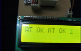
This project is an extension of interfacing microcontroller with hyperterminal and GSM module. The previous project explained a way to interface a GSM [[wysiwyg_imageupload::]]module with 8051 microcontroller where the information response and result codes received by the controller were sent back to computer to display them at HyperTerminal. In this project, the same output is displayed on a 16×2 LCD interface. This project is first step towards making and independent system using the GSM module and a microcontroller. Here the HyperTerminal (computer) has been replaced with LCD at the output end. In the next project (MC076), the AT Commands will be transmitted to the GSM module by the microcontroller itself thus avoiding the need of using HyperTerminal entirely. This project adds a feature to display the information response and result codes on a 16×2 LCD in response to the AT commands sent through the HyperTerminal of computer. The characters typed at HyperTerminal get transmitted serially through the transmit pin (Tx) of RS232 interface.
How to interface RFID with 8051 microcontroller (AT89C51)- (Part 34/45)
An RFID (Radio-frequency identification and detection) reader is a device which is used to communicate with RFID tags by receiving and transmitting signals. These signals use radio waves for wireless communication. RFID tag is applied to products, individuals or animals to identify and track them. The identification is done through a unique serial number. This topic covers the…
Clock using RTC DS12C887 & 8051 microcontroller (AT89C51) with alarm set function
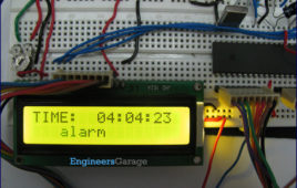
DS12C887 is a real time clock (RTC) IC from Dallas Semiconductors. The RTCs provide precise time and date information. This article explains the making of a [[wysiwyg_imageupload::]]digital clock with alarm setting functionalities. RTC has been interfaced with AT89C51 to perform desired operations. This project is an improvement over Digital clock using RTC DS12C887 and 8051 microcontroller (AT89C51) with time set and has the alarm setting function also. The alarm setting function allows user to set the alarm. The clock time is displayed on the LCD. The free source code for the program is available in C.The circuit for interfacing the RTC and 16×2 LCD with the microcontroller 8051 is shown in the circuit diagram. Port P2 is set as data port for LCD to send the data on the LCD while port P0 is set as data port for the RTC DS12C887.
Dual message display on LCD using 8051 microcontroller (AT89C51)
This article presents an interesting approach for sound activated display system. This system displays two different messages for odd and even number of [[wysiwyg_imageupload::]]sounds. When the sound is produced for the first time the first message is displayed on the LCD. At the second sound, a second message is displayed. The first message reappears at the third sound. Thus alternate messages are displayed every time a sound, say clap, is detected by the system. The project is build around the 8051 microcontroller (AT89C51) along with LCD and a condenser microphone.The circuit consists of four major modules, namely, a sound sensor, an amplifying circuit, a control circuit and a display module. A switching circuit is also employed after the amplifier. Any sound, say clap, is detected by a microphone (condenser mic) which acts as the sound sensor. This mic is connected to a two stage transistor amplifier. The mic output is thus amplified to a suitable level so that it can be detected at the TTL logic.
Sound operated display on LCD using 8051 microcontroller
This is an interesting idea in which a message is displayed on an LCD screen whenever a sound is produced. The message remains on LCD for a short duration of [[wysiwyg_imageupload::]]time and then disappears. This topic demonstrates the interfacing of a sound operated circuit and LCD display with the 8051 microcontroller (AT89C51). The circuit can be used to display welcome message at entrance; or warning messages at public places. It can also be used to aid communication for deaf and dumb people.The circuit consists of four major modules, namely, a sound sensor, an amplifying circuit, a control circuit and a display module. A switching circuit is also employed after the amplifier.Any sound, say clap, is detected by a microphone (condenser mic) which acts as the sound sensor. This mic is connected to a two stage transistor amplifier. The mic output is thus amplified to a suitable level so that it can be detected at the TTL logic.
Celsius and Fahrenheit scale digital thermometer using 8051 microcontroller (AT89C51)
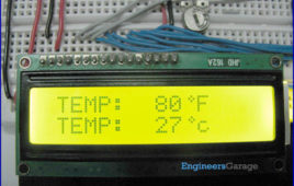
Fahrenheit scale digital thermometer is a temperature indicator which displays temperature in Fahrenheit scale. It is similar to Celsius scale digital thermometer, [[wysiwyg_imageupload::]]except a little modification in the microcontroller program. The temperature sensed in Celsius scale in the Celsius scale thermometer project is converted into the Fahrenheit scale temperature just by using the Celsius to Fahrenheit conversion formulae. This project also uses 8051 microcontroller (AT89C51).A digital thermometer can be easily made by interfacing a temperature sensor to the microcontroller AT89C51. The temperature sensor used in the project isLM35. The LM 35 IC generates a 10mV variation to its output voltage for every degree Celsius change in temperature. The Output of the temperature sensor is analog in nature so we need an analog to digital convertor for converting the analog input to its equivalent binary output. The ADC 0804 is the analog to digital convertor IC used in the project. 0804 is a single channel convertor which converts the analog input up to a range of 5V to an equivalent 8-bit binary output.