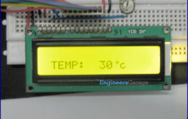
Celsius scale thermometer displays the ambient temperature through a LCD display. It consists of two sections. One is that which senses the temperature. This is a temperature sensor LM 35. The other section converts the temperature value into a suitable number in Celsius scale which is done by the ADC0804. A digital thermometer can be easily made by interfacing…
Electronic code lock with user defined password using 8051 microcontroller (AT89C51)
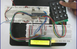
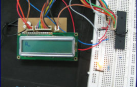
An electronic lock or digital lock is a device which has an electronic control assembly attached to it. They are provided with an access control system. This [[wysiwyg_imageupload::]]system allows the user to unlock the device with a password. The password is entered by making use of a keypad. The user can also set his password to ensure better protection. The major components include a keypad, LCD and the controller AT89C51 which belongs to the 8051 series of microcontrollers. This article describes the making of an electronic code lock using the 8051 microcontroller. A 4×3 matrix keypad and a 16×2 LCD have been used here. Keypad and LCD are very commonly used input & output devices, respectively. A four digit predefined password needs to be specified the user. This password is stored in the system.While unlocking, if the entered password from keypad matches with the stored password, then the lock opens and a message is displayed on LCD. Also an output pin is made high to be used for further purpose.
Digital alarm clock using LCD and 8051 microcontroller
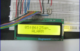
An alarm clock is a clock that indicates a pre-set time by producing sound at that time. This functionality of digital clock is used to awaken people or remind them [[wysiwyg_imageupload::]]of something. This circuit is an extension to the digital clock with time setting option. Here an extra switch is provided to set the alarm. While the alarm is set, the clock time does not stop and runs in the background.The circuit is build around 8051 microcontroller (AT89C51) and uses LCD to display time. This is an improved version of digital clock with LCD display. It has an extra feature to set the alarm in the starting. On reset, the LCD prompts the user to set alarm. Only the hour and minute components can be set by pressing the corresponding switches, repeatedly. These switches are made active low and so they provide ground to the corresponding input pins of the microcontroller AT89C51. The AM/PM mode is set by toggling the switch between ground and Vcc. Ground would set the clock in AM mode while Vcc would set it in PM mode.
Digital clock using LCD and 8051 microcontroller
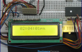
A digital clock is one that displays time digitally. The project explained here, displays time on a 16×2 LCD module. The LCD is interfaced with 8051 [[wysiwyg_imageupload::]]microcontroller (AT89C51). This circuit can be used in cars, houses, offices etc. This clock works in 12 hour mode and is configured by programming the microcontroller AT89C51. The program uses a delay function for producing a delay of 1 second.The connections in the circuit are as following: port P2 of microcontroller is used as data input port which is connected to data pins (7-14) of LCD. P3^0, P3^1 and P3^6 pins of microcontroller are connected to control pins RS, RW and EN of LCD. P1^0, P1^1, P1^2 and P1^3 pins of microcontroller are connected to tactile switches to take manual inputs. Read more to find out how to interface the clock and code the module.
Electronic Voting Machine using LCD and 8051 microcontroller
Electronic voting machine has now replaced the traditional mechanism of voting due to several advantages like security, automatic counting etc. This project [[wysiwyg_imageupload::]]presents a way to develop an electronic voting machine which displays the count of votes on a 16×2 LCD interface. A user can get his/her vote register through a set of switches (one for each candidate). After every cast of vote, the subsequent count can be seen on LCD. The circuit uses AT89C51microcontroller and the code for the project has been written in C. This LCD based electronic voting machine is designed for four candidates. The input part consists of a set of six tactile switches. The switches and 16×2 LCD are interfaced to microcontroller AT89C51 for various operations and displays.The provision of casting votes for the candidates has been provided through four of these switches. These switches are made active high and connected to pins 2-5 (P1^1 – P1^4) of the controller. The remaining two switches (both active low) are to start and stop the voting procedure.
How to display custom animations on 16×2 LCD using 8051 microcontroller (AT89C51)- (Part 12/45)
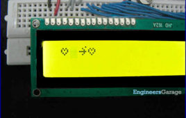
Animating custom made characters on a 16×2 LCD screen can be very exciting. This topic explains the principle and operation of a displaying animation on LCD [[wysiwyg_imageupload::]]using Microcontroller AT89C51. There’s a useful side effect to the way the LCD controller uses CG RAM. Normally, we define a pattern in CG RAM, and then print the character. But it is also possible to change the CG RAM for characters that are already on the screen, and their appearance will change. Before animation, the custom characters of heart, cutting heart, blank screen and arrow should be stored at different addresses. (for more detail about CG RAM and LCD refer LCD custom character and LCD interfacing).The connections in the circuit are as follow: the output of controller (from port P2) goes to data pins of LCD numbered 7-14. The control pins RS (pin4), R/W (pin5) and EN (pin6) are connected to the pins 0, 1 and 6 of port P3 (P3^0, P3^1 & P3^6, respectively).
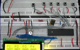
How to display Hindi alphabets on 16×2 LCD using 8051 microcontroller (AT89C51)- (Part 11/45)
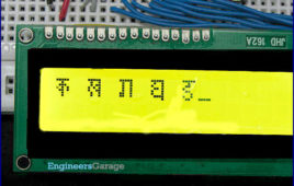
The conventional way of displaying a character or text on a 16×2 LCD uses English alphabets. But with the concept presented here, it is possible to display Hindi alphabets as well. The idea is to create custom characters on a 5×8 pixel matrix element corresponding to Hindi letters. These letters once created can be invoked and displayed as and when desired by interfacing LCD with AT89C51. There are 8 symbol locations in LCD ” , the bitmap values are mapped to first base address location 64 (ASCII code 0).This is achieved by first sending the address location (64) to LCD command register. Next, the bitmap values (31, 4, 14, 21, 13, 4, 4, 0) are sent to the LCD data register.
How to create text animation on 16×2 LCD using 8051 microcontroller (AT89C51)- (Part 9/45)
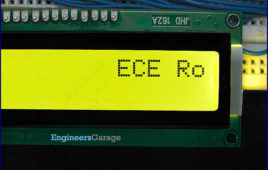
A static message can be displayed on a 16×2 LCD by interfacing it to the microcontroller (AT89C51). The same message can also be displayed with certain [[wysiwyg_imageupload::]]animated effects like moving, blinking etc. This topic explains how to create dynamic effects with the text displayed in LCD. A string or message can be displayed on LCD by sending its characters to data register after configuring the command register of LCD. To create dynamic effects, a specific command instruction is sent to LCD via microcontroller AT89C51. To create a particular effect, any of these code(s) can be used in a pattern. For example, shifting the entire display right (5H) in a loop will keep moving the text to right. To create oscillating text, first keep shifting the string to right (for say, 8 positions) and then shift it to left. This left-right shifting can be done in an infinite loop.Here P2 is used as output port of the 8051 microcontroller (AT89C51) which sends the data byte to data pins of the LCD. The control pins (pin 4, 5 & 6) are connected to pins 0, 1 & 6, respectively, of P3 port of the microcontroller. Pin 3 is connected to a preset of 10k to adjust the contrast on LCD screen.
How to display number on 16×2 LCD using 8051 microcontroller (AT89C51)- (Part 8/45)

LCD is a very commonly used output device to display alphanumeric characters. The LCD displays the character corresponding to the data received on its input [[wysiwyg_imageupload::]]data port i.e., it treats the data as the ASCII value of the character to be displayed. So if the value 65 is given to its data port the character “A” will be displayed and if the value 49 is given to the LCD the numeric digit “1” will be displayed. At many instances it is required to display a number like 123 on LCD. Displaying this number is tricky. If the data port of the LCD is loaded with the number 123, then the character corresponding to it will be displayed. This article shows the concepts behind displaying a number on LCD.The article uses 8051 microcontroller (AT89C51) to demonstrate the above principle. The circuit is divided into two units: the controller unit and the display unit. The controller unit consists of a microcontroller circuit. The microcontroller used here is AT89C51 (for details of controller circuit, refer ‘led blinking’ section).
How to display text on 16×2 LCD using 8051 microcontroller (AT89C51)- (Part 7/45)
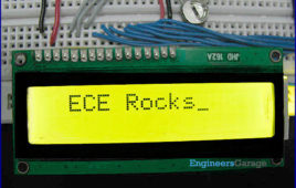
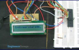
Several electronic devices and projects require a message to be displayed in order to indicate their functioning. This topic explains how to display a message [[wysiwyg_imageupload::]](string) on 16×2 LCD by interfacing it to 8051 microcontroller (AT89C51). A single character can be displayed on LCD by properly configuring its data and command registers. A string is nothing but a sequential arrangement of several characters that can be displayed on LCD by using the following algorithm. Here P2 port of the microcontroller is used as output port which sends the data byte to data pins of the LCD. Read more to find out how LCD is interfaced with the microcontroller and how does the circuit work.
How to interface 16×2 LCD with 8051 microcontroller (AT89C51)- (Part 6/45)
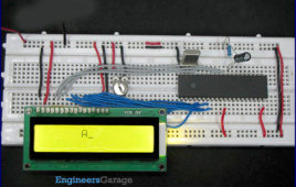
It is very important to keep a track of the working of almost all the automated and semi-automated devices, be it a washing machine, an autonomous robot or [[wysiwyg_imageupload::]]anything else. This is achieved by displaying their status on a small display module. LCD (Liquid Crystal Display) screen is such a display module and a 16×2 LCD module is very commonly used. These modules are replacing seven segments and other multi segment LEDs for these purposes. The reasons being: LCDs are economical, easily programmable, have no limitation of displaying special & even custom characters (unlike in seven segments), animations and so on. LCD can be easily interfaced with a microcontroller to display a message or status of a device. This topic explains the basics of a 16×2 LCD and how it can be interfaced with AT89C51 to display a character. A 16×2 LCD means it can display 16 characters per line and there are 2 such lines. In this LCD each character is displayed in 5×7 pixel matrix. This LCD has two registers.
How to interface LCD in 4 bit mode with AVR microcontroller- (Part 10/46)
This article explains interfacing of LCD with ATmega16 using 4-bit mode. In this mode only four pins are used for sending data and command instructions. This [[wysiwyg_imageupload::]]mode has the advantage over the 8-bit mode as it uses less number of pins. The remaining pins of the controller are available for normal use. The Data or command is sent in nibble form (1 nibble= 4 bit) in the 4-bit mode. The higher nibble is sent first followed by the lower nibble. The function of RS, RW and EN pins remains similar to 8-bit mode. The LCD can be configured in 4-bit mode by sending appropriate instruction which is called “Function set” to it. The Function set is hexadecimal instruction for LCD MPU unit, which selects working modes of LCD. Continue reading to find out LCD can be interfaced with simple programming and circuitry.
How to display text on 16×2 LCD using AVR microcontroller (ATmega16)- (Part 8/46)
This article is in continuation to the article Single character LCD display using AVR. The aforesaid article shows how to display a single letter on LCD. Moving [[wysiwyg_imageupload::]]forward towards learning to work with LCD, this article explains how to display a string on LCD. Displaying string is occasionally used in many applications. The connection of the LCD with the AVR microcontroller (ATmega16) is shown in the circuit diagram. A string is nothing but a sequence of characters. The following steps explain how to display a string on the LCD. Keep on reading to find out How to code and interface in order to display text on 16×2 LCD using AVR microcontroller (ATmega16).
How to interface 16×2 LCD with AVR microcontroller (ATmega16)- (Part 7/46)
LCD is used to present textual information to the users. It is great fun to work with LCD. Also LCD makes your application more interactive. LCD comes in various [[wysiwyg_imageupload::]]configurations and the most popular one is 16×2 matrix display. This article shows the interfacing of ATmega16 with LCD by displaying a simple character on the LCD. For more information about LCD, refer the article LCD interfacing. In this project LCD is working in 8-bit mode i.e., the data transferred to the LCD must be in 8-bit data form. The PortA of ATmega16 is connected to data pins of LCD and is defined as LCD_DATA. PortB is defined as control pins (Rs, R/W and En). Conceptually, interfacing LCD with AVR microcontroller is similar to that of interfacing it with any other microcontroller. Continue reading to understand interfacing circuitry and coding concepts of the project.
How to display text on 16×2 LCD using PIC18F4550 Microcontroller- (Part 6/25)
In Several automated and semi-automated devices require a message to be displayed in order to indicate their working status. In continuation to LCD interfacing [[wysiwyg_imageupload::]]with PIC18F4550, this article explains how to display a message or string on a 16×2 character LCD. In the previous article, a single character was displayed on LCD by properly configuring its data and command registers. A string is nothing but a sequential arrangement of several characters that can be displayed on LCD by using the programming steps mentioned here. The circuit connections and user-defined functions are same as earlier. The LCD data pins are connected to PortB of PIC18F4550 while the control pins are connected to first three pins. Read more to find how easily can one interface a display unit with a PIC micro controller.
How to interface LCD with PIC18F4550 Microcontroller- (Part 5/25)
For basic details and operations of character LCD, refer LCD interfacing with 8051. Here LCD has been interfaced in 8-bit mode* with data pins (D0-D7) connected to PortB of PIC18F4550. The LCD control pins RS, R/W and EN are connected to PortA pins RA0, RA1 and RA2 respectively. *Character LCD can also be interfaced…
Digital Book Cricket with ATtiny 85
The project described here is a digital implementation of “book cricket game” which students normally use to play in their childhood time. The heart of the project is 8 bit MCU from AVR family called ATtiny85. ATtiny85 are small and cheap microcontrollers which are convenient for running simple programs with low footprint. The software used for programming the MCU is Ardunio which is a popular open source IDE. The overall design is kept to a least for simplicity and ease to use. The main components used in the circuitry are 16X2 LCD which is used to display the characters in 2 lines with maximum of 16 characters in one line, a serial in parallel out shift register HEF4094, ATtiny85, 2 push buttons and 7805 voltage regulator which regulates the voltage supply to maximum of 5 volts. Shift register HEF4094 is used because normally when LCD is used it requires 7 connections to the pins on the display. But if shift register is used the number of connections to the MCU can be reduced to only 3 wires.
Remote Stepper Motor controller with LCD
Second application of IRRCS and probably the most interesting application because it includes everything remote control, 89C51 based stepper motor control, LCD display. 89C51 controls all three parameters (RPM, direction, no. of revolutions) of bipolar stepper motor and also indicates every action on LCD. Know how to interface LCD with microcontroller 89C51 Know how…
Multi Digit Wireless Password Lock with LCD
This is a complete different application from any other applications you have seen till yet. With this unit you can activate or deactivate any application/device with the use of password only. Means to activate any device/application first you need to enter correct password. If you don’t device won’t be activated. you must have seen such…
Timer Operated Relay with Digital Display
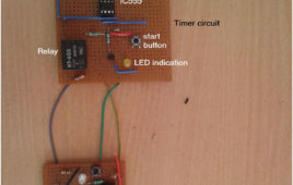
The circuit presented here operates a relay for Fixed Timer Interval. So the device or machine connected with relay operates for same time. The device once switched ON, automatically switches OFF after Fixed (set) Time Interval when relay switches OFF. The Time Interval can be varied and it is displayed on 7 Segment Display. This kind of circuits can be used in many applications where it is required to operate any device or machine for Fixed Time Interval. Like· The Alarm Signal (or Bell) once triggered, remains ON for Fixed Time Interval and then shuts off automatically· In Manufacturing Industries the Motors have to be rotated for Fixed Time Interval once start button is pressed. It stops automatically when time period is overTime operated relay circuit is build using IC555. To display the time period in seconds 2-digit decade counter is build using CD4026 chip. Another IC555 is used to provide 1 Hz pulse to update time period after every 1 sec.