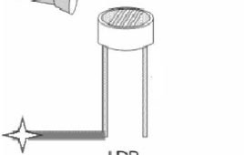
Ever imagined how the street lights get turned ON automatically in the evening and gets switched OFF in the morning? Is there anyone who comes early morning to turn off these lights? The following circuit can perform this job properly. This project uses the output from a simple light/dark activated circuit known as LDR (Light Dependent Resistor) and drives a relay in its output which can be further coupled to switch on/off an electrical appliance in a household. An appliance can be made dark or light activated by slightly changing the circuit’s configuration. This idea finds numerous applications such as, automatic watering of gardens in evening, automatic night lamp, dark activated siren and so on.
Automatic Night Light Control
Automatic night light control system needs no manual operation for switching ON and OFF when there is need of light. It detects itself whether there is need for light or not. When darkness rises to a certain value then automatically light is switched ON and when there is other source of light i.e. day time, the light gets OFF. In the project we use light detecting resistor as a light sensor & a NAND gate for detection of high level or low level of voltage to energize the RELAY coil which is used to interface the control circuit with the external light source.
How to interface LDR with ADC0808 using interrupt clock from 8051 microcontroller (AT89C51)- (Part 26/45)

This circuit demonstrates the principle and operation of interfacing an LDR with ADC0808 using the controller AT89C51. This is an 8 channel ADC i.e., it can take [[wysiwyg_imageupload::]]eight input signals. The output is displayed on the LCD. ADC0808 is an 8-bit resolution IC with eight input pins. LDR is used to provide the analog input. The output of the LDR is displayed on a 16×2 LCD. A clock of frequency 500 KHz is generated using Timer0 in the interrupt mode. To enable the interrupt, the value of the register IE is set to 0x82.The output pins of ADC are connected to the port P0 of the AT89C51. The pin10 of the ADC is connected to pin8 (P1.7) of the controller for clock input. ALE, pin22 of the ADC is connected to pin1 (P1.0) of controller. OE, pin9 of the ADC is connected to pin4 (P1.3) of controller. SC, pin6 of the ADC is connected to pin2 (P1.1) of the controller. EOC, pin number 7 is connected to pin 3 (P1.2) of controller.
Color distinguished using LDR/Color sensor using LDR
This circuit can be used to sense and differentiate between different colors. This project demonstrates the principle and operation of a simple color sensor [[wysiwyg_imageupload::]]using LDR. The circuit is divided into three parts: Detector (LDR), Comparator and Output. In this project, when light of a particular color falls on LDR, its resistance decreases and an output voltage is produced. This voltage is dependent on the intensity and wavelength of different color. For this we need to set reference voltage of comparator according to our requirement. Keep on reading to find out how the circuit is assembled and how it works.
Shadow Alarm using LDR

Shadow alarms are widely used for security purposes. A shadow alarm is a device that generates an alarm whenever a shadow falls on it. This project can be easily [[wysiwyg_imageupload::]]installed on the windows and doors. This circuit demonstrates the principle and operation of a simple shadow alarm using LDR. Other than the LDR, the circuit consists of LEDs for input and output purposes, buzzer and a LM324 comparator IC. Keep on reading to find out how the circuit is constructed and how it can be made to work.
Opamp LM324 as comparator using LDR
This project based on op amp comparator circuit demonstrates the principle of operation of op amp (operational amplifier) as comparator. A comparator [[wysiwyg_imageupload::]]compares two voltages fed to it and gives output correspondingly. This circuit finds application as intermediate circuit in numerous circuits where there is need to compare two voltages. This Op amp comparator circuit project uses opamp (IC LM324) as comparator. The output of the comparator is high if voltage at positive end is more than voltage at negative end and gives low output if voltage at positive end is lesser than negative end. Read more to find out how this op-amp comparator circuit works and how it can be constructed in an efficient manner.
Darkness detector using LDR and astable mode of 555 timer IC
This circuit based project demonstrates the principle and operation behind the darkness detector. For example lamps which switch on automatically in the night. [[wysiwyg_imageupload::]]Various decoration lights are needed to be switched on automatically in dark. The circuit described here is more of a sensor application with a speaker attached to it as output. However, depending upon the application, user can attach a night lamp or series of small LEDs to the circuit too. Constructed around a 555 timer IC and LDR, this circuit uses a 9V battery as a power source along with a couple of passive circuit components: resistance and capacitance. In this circuit 555 works in astable mode producing a frequency of about 56 hertz. Keep on reading to find out how the circuit is assembled and how it works.
Simple LDR Dark Sensor Circuit
The circuit described here stops the musical sound when darkness is detected like when you put your hand above the sensor. This circuit can be used as morning alarm. Install it on your window so when the light falls on it will start giving you melodious sound to wake up. In night you can use it to switch off the light of staircase. When you switch off the light of your room with little modification like you can connect relay at output (in place of speaker) to off the bulb. This circuit can be operated with pencil cell as it require less only 3V for its operation. It can easily be mounted because of number of components used in circuit are quite small. LDR is a device whose sensitivity depends upon the intensity of light falling on it.
Picnic Lamp (White LED Lamp)
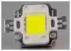
This simple White LED lamp switches on when its surroundings turn dark. It is an ideal portable lamp in picnic sites. It uses solar energy for charging the battery and an LDR for automatic switching. 6 Volt 100 mA solar panel is used to charge the battery during day light. During day time, the…