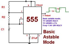
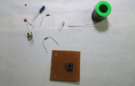
The 8-LED Flasher is built around Timer and Counter ICs. It Flashes 8 LEDs sequentially and the flashing speed can be controlled by a potentiometer. This can be used as a design pattern for decoration. But theoretically, it clears the Timer and Counter concepts in an easy way.The circuit comprises of various components like 555 Timer IC, Decade counter (CD4017), LEDs, Resistors, Capacitors, Wires & a 9V battery. The monolithic integrated circuit 555 timer can be used as square-wave generator, linear saw-tooth generator, pulse generator, time delay generator, etc. here we use it to generate square waveform i.e. it is used in the Astable Mode with a duty cycle of 66.6%.The 8 LEDs could be arranged in any pattern and thus be used as a decorative Light Toy in your living room.
8 LED Flasher with Flashing Speed Control
The 8-LED Flasher is built around Timer and Counter ICs. It Flashes 8 LEDs sequentially and the flashing speed can be controlled by a potentiometer. This can be used as a design pattern for decoration. But theoretically, it clears the Timer and Counter concepts in an easy way.The circuit comprises of various components like 555 Timer IC, Decade counter (CD4017), LEDs, Resistors, Capacitors, Wires & a 9V battery. The monolithic integrated circuit 555 timer can be used as square-wave generator, linear saw-tooth generator, pulse generator, time delay generator, etc. here we use it to generate square waveform i.e. it is used in the Astable Mode with a duty cycle of 66.6%.The 8 LEDs could be arranged in any pattern and thus be used as a decorative Light Toy in your living room.
DIY- Heart Shape LED Light Flasher
Ever wanted to gift something “Electronically Special” to your loved ones? This article will show you how to make such gift in an Engineer’s style. All we need is a 555 Timer IC and a couple of other electronic components to make this LED Heart Flasher.Basically, the 555 Timer IC is made to work as an “Astable Multi-vibrator” here. We need at least 12 LEDs to make the shape of a heart and a 555 IC is not capable of directly driving 12 LEDs at a time. So that is why we have used a medium power transistor 2N3019 which can drive loads up to 1 Ampere. The transistor works as a switch here and the output from the 555 IC provides the switching signal to the transistor. We’ll be driving the circuit using 6 volts.And one more advantage of this circuit is that you can customize the frequency and Pulse width of the signal by changing the value of the resistors and capacitors
Led Flasher Circuit
The operation of the LED flasher circuit project is based on 555 timers with few other components. It flashes the LED ON and OFF after regular intervals of [[wysiwyg_imageupload::]]time. It can be used as eye of a toy to find the toys in the dark, in events like wedding ceremonies, birthday parties or any other events to grab the attention. The LED Flasher circuit project here is based on 555 timers. The timer is wired in astable mode which means that its output is a square wave oscillator. The two LEDS are connected in such a way that when one is ON other is OFF and vice versa. Keep on reading to find out how the circuit is constructed and how it works.


