Assemble the circuit properly. The switch we are using is push to make switch means when you press the switch it conducts and when you release the button switch become disconnected. In our circuit correct code is S1, S3, S5, S8 by pressing this Fig. 2: Protoytpe of Electronic Lock using Switches Circuit on Breadboard…
Electronic Code Lock Circuit
In this circuit we are using 6 switches. If switch S1 to S4 are pressed sequentially then lock will be opened. Switch S5 is the reset switch while switch S6 is used to disable the circuit. You can also increase the number of disable switches by connecting more switches in parallel with S6. One must…
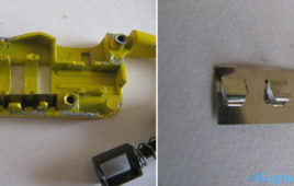
Insight – How Mechanical Lever Lock Works
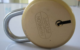
With every possession comes a natural urge to protect it with all the might, protect it with every possible barrier that he could invent. One of the last bulwarks to this line of security has been the simple yet efficient, padlock. Padlocks were one of the very first mechanical inventions that were designed to protect the assets and houses. A very high degree of key specificity makes the chances of having one key working with more than one lock highly unlikely. In order to use it, there is no complicated mechanism unlike setting a password of 6 characters or more and then always remembering them, but a simple key. All one has to do is to insert appropriate key to engage or release the lock. Simple enough? But is it really that simple from the inside? Let’s find out. Why does every lock has its own unique key?
Insight – How Number Combination Lock works
Number combination lock is like a mystery game of combinations and sequences. With the use of mathematical logics and basic laws of physics (balancing of forces) the old traditional padlocks have been replaced by new and modified number combination lock. Padlocks are the portable locks that were designed to defend against any theft, vandalism or sabotage but with passage of time they became part of day to day life as a safety measure. Padlocks used earlier were heavy and required key to unlock but with number combination lock it becomes easy to handle the system as only thing that is required is a code which can activate or deactivate the lock. Now, all one has to do is set their code and activate the lock. Let’s take the insight of number combination lock in the following section stepwise from its outer parts to the innermost components.
Electronic code lock with user defined password using 8051 microcontroller (AT89C51)
An electronic lock or digital lock is a device which has an electronic control assembly attached to it. They are provided with an access control system. This [[wysiwyg_imageupload::]]system allows the user to unlock the device with a password. The password is entered by making use of a keypad. The user can also set his password to ensure better protection. The major components include a keypad, LCD and the controller AT89C51 which belongs to the 8051 series of microcontrollers. This article describes the making of an electronic code lock using the 8051 microcontroller. A 4×3 matrix keypad and a 16×2 LCD have been used here. Keypad and LCD are very commonly used input & output devices, respectively. A four digit predefined password needs to be specified the user. This password is stored in the system.While unlocking, if the entered password from keypad matches with the stored password, then the lock opens and a message is displayed on LCD. Also an output pin is made high to be used for further purpose.
Simple Electronic Lock using Keypad and 8051 microcontroller
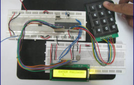
There are several electronic devices which require a security lock for their protection. This article describes a way to build an electronic lock with a four-digit [[wysiwyg_imageupload::]]password. A keypad, interfaced with 8051 microcontroller (AT89C51), is used to enter the password. The password and its status are displayed on an LCD screen.A 4×3 matrix keypad and a 16×2 LCD have been used here. Keypad and LCD are very commonly used input & output devices, respectively. A four digit predefined password is specified in the microcontroller AT89C51’s program. If the entered password from keypad matches with this password, then the lock opens and a message is displayed on LCD. Also an output pin is made high to be used for further purpose. The connections in the circuit are as following: port P2 of microcontroller is used as data input port which is connected to data pins (7-14) of LCD. Read more to find out how does the circuit works.
Multi Digit Wireless Password Lock with LCD
This is a complete different application from any other applications you have seen till yet. With this unit you can activate or deactivate any application/device with the use of password only. Means to activate any device/application first you need to enter correct password. If you don’t device won’t be activated. you must have seen such…


