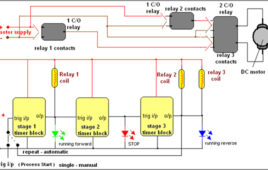
In most of the industrial processes it is required to rotate DC (or AC) motor forward and reverse for desired time. First motor rotates forward (clockwise) for some time (say 2 – 3 min) then it stops for some time. Again it rotates reverse (anticlockwise) for some time and rests. This process repeats every time when gets triggeredSequential timer is widely used circuit in industries because in most of the industries all the processes are of chain reaction type. That means one process ends and it triggers next. The last process triggers first process when it ends. And thus the cycle continues. These sequence timers are micro controller based multi-functional and programmable.But here we have a sequential timer using simple IC555. So let us see how it is done
Wireless DC Motor Speed Control using IR and IC555

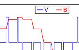
This is a very interesting application. We shall vary the speed of DC motor from a remote place without any wire connection. I am using PWM (pulse width modulation) method to very the speed of DC Motor. To make it wireless I am using IR transmitter and IR sensor. There are two sections in the circuit 1) PWM generator with IR modulator and 2) IR receiver and motor driver. Transmitter generates PWM wave of 50 Hz (20 ms) and modulates it over 38 KHz frequency. The IR sensor on receiver side will demodulate the PWM wave and drives the DC motor.
Wireless Stepper Motor Speed Control using Laser and IC555
An interesting project explaining how can one control speed of a stepper motor from a remote place without using any wires. A LASER and LDR are used for this purpose. From the transmitter, low frequency pulses are sent to the receiver using LASER diode. On the receiver side, a LDR will receive these pulses which will further trigger mono stable multi-vibrator to regenerate same pulses. These pulses will drive the stepper motor through driver circuit. So as anyone changes pulse frequency from transmitter, the stepper motor speed will change accordingly. The project uses a pulse generator, LASER, LDR, monostable multi-vibrator, current drive, stepper motor, counter and OR gates.
Line Follower Robot

Line follower is an autonomous robot which follows either black line in white are or white line in black area. Robot must be able to detect particular line and keep following it. For special situations such as cross overs where robot can have more than one path which can be followed, predefined path must be followed by the robot. In the following section, we will discuss the line follower robot which follows black line in white area and take right turn whenever cross overs or Y shaped turn arrives.However with some minor suitable changes, users can make robot for other possibilities also.
Insight – How Electric Beard Trimmer Works
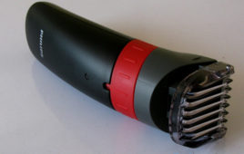
We currently live in the era of speed and sophistication. Everything that man once developed and found to be too time consuming and cumbersome has been modified, altered and compacted to make its use more simple. To cope up with this speed, every routine work has been automated. This pursuit of professional excellence has forced people to spend less time on themselves. For example, shaving is almost a daily chore for men to ensure personal hygene and needs to be done fast. But doing so with manual razors is a time consuming job and if done to hastily, can lead to cuts and burns.But thankfully, the technology of this age offers replacement to old age instruments like manual razors and frequent visits to a barber shop by time effective handheld devices like hair clippers and beard trimmers. Unlike manual razors and scissors, trimmers are devices that cut, but don’t bite and that too in very less time.
Insight – How Geared DC Motor works
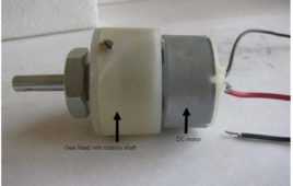
Geared DC motors can be simply put as an extension of DC Motor. The speed of the motor is counted in terms of rotation of the shaft per minute and is termed as RPM .Simple DC motors are restricted in terms of power and lack proper speed control. They can even run at speeds approximately close to 3,000 RPM which might get beyond the desired requirements of the user. However, using a geared motor can reduce down the RPM such as 150 and lower, hence providing more torque to the machine. This concept where gears reduce the speed of the vehicle but increase its torque is known as gear reduction. This Insight will explain those major as well as minor details that make the gear head and hence the geared DC motor work.
Simple TRIAC Controlled Ceiling Fan
Conventional Ceiling fans operate with voltage divider circuit. Alternatively Ceiling fans can even be operated with Silicon Controlled Rectifiers TRIAC, and 555 timer circuits. This circuit is very cheap in its build. Circuit Diagram Tab 1 shows the TRIAC ceiling fan circuit while circuit diagram tab2 details with the power supply. Working The 230V 50Hz supply…
Temperature Controlled Fan
A simple project using microcontroller AT89S51 to control the speed of 12V fan according to the surrounding temperature. In this project we use the concept of PWM (pulse width modulation) to increase or decrease the speed of fan. We also interface 2*16 characters LCD which shows the outside temperature through the temperature sensor. Followings are…
Insight – How stepper motor works
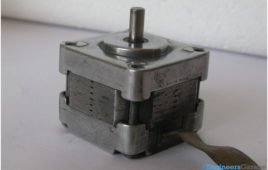
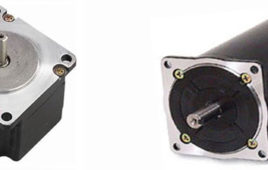
Like other motors a stepper motor also converts the electrical power into mechanical rotation. A stepper motor rotates in distinct steps where each step is a fraction of a full circle. Stepper motors are driven with pulses and one set of pulses can move the stepper motor by one step only.The top and bottom mounting plates made up of aluminum with stator in between. The rotor shaft and wires are coming out. A Stepper motor has a stator and a rotor. The rotor has a permanent magnet attached to it. The stator is made up of coils as shown in the image. There are eight coils in this motor. Every coil in the motor behaves as an electromagnet, when they are energized by electrical pulses.
Electric Cars
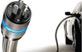
What would the cars run on if one day the fuels that we’ve been lavishing on for so long just disappeared? Earth had once been a planet replete with stockpiles of consumable fossil fuels like coal and petroleum. But as mankind progressed and advanced its appetite for energy shot up to humungous proportions and in much less than three centuries since the Industrial revolution, there is an outcry to conserve these natural resources and look for alternatives. Of all the industries that would directly or indirectly hit the consumers if these fuels disappeared from earth, the most obvious would be the automobile industry. To offer a viable solution to these dilemmas, many innovations in the field of automobile industry have taken place from time to time. One of them is ‘electric cars’, a solution for a cleaner and healthier tomorrow.
Insight – How Servo Motor works
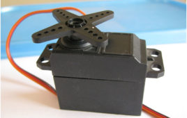
Servo Motors are DC Motors with a servo mechanism to provide a precise angular motion. Pulse width modulation (PWM) technique is used to set the angle of rotation. Generally RC servo motors have a rotation limit of 900 to 1800 but servos with high rotation angles are also available.A DC motor and the potentiometer which is used to provide feedback to the electronic circuitry. It is connected with the DC motor with the help of gear assembly. As soon as the motor starts rotating the potentiometer also starts rotating and the output of potentiometer i.e. voltage across the middle terminal changes which acts as the feedback signal to indicate the degree of rotation of the motor.
How to interface Stepper Motor with PIC18F4550 Microcontroller- (Part 13/25)
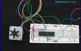
A Stepper Motor is a brushless, synchronous DC motor which divides a full rotation into a number of steps. For detailed information on working, types and stepping modes, refer the article on Stepper Motors. Here the operation of a unipolar Stepper motor with PIC18F4550 microcontroller has been explained.As stated earlier, a Stepper motor rotates step by step. Each stepper motor has a defined step angle which is the minimum degree of rotation in a single step. This step angle depends on the internal construction of the motor. If a stepper motor has a step angle of 1.8°, then it would need 200 steps for a complete circular rotation. For control operation, construction and stepping modes, refer the article on Stepper Motors.The stepper motor consists of a Rotor and four Stators. The stators are rounded with center-taped winding. The center-taped terminals are known Common terminals. Thus a unipolar stepper motor consists of total 6 wire-ends (four wires for coils and two for the common ends).
How to interface Servo Motor with PIC Microcontroller- (Part 21/25)

Servo systems use the error sensing negative feedback method to provide precise angular motion. Servo Motors are used where precise control on [[wysiwyg_imageupload::]]angular motion is needed. Servo motors are widely used in the field of Robotics to design robotic arms, palms, legs and so on. They are also used in RC toys like RC helicopter, airplanes and cars.The interfacing of servo motor using PIC microcontroller has been explained here. Readers are advised to go through the article on Servo Motors to learn basic mechanism and control of servo motor.A Servo motor has three wire terminals : two of these wires are to provide ground and positive supply to the Servo DC motor, while the third wire is for the control signal. These wires of a servo motor are color coded. The servo motor can be driven only when PWM (pulse width modulated) signals are provided to the control terminal. The total pulse duration for a typical servo motor should be of 20 milliseconds. The on-time duration of the control signal varies from 1ms to 2ms. This on-time variation provides angular variation from 0 to 180 degree. Also refer Servo motor control using 8051.
Insight – How DC Motor Works
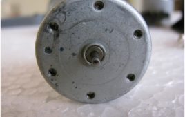
DC Motors convert electrical energy (voltage or power source) to mechanical energy (produce rotational motion). They run on direct current. The DC motor works on the principle of Lorentz force which states that when a wire carrying current is placed in a region having magnetic field, than the wire experiences a force. This Lorentz force provides a torque to the coil to rotate.When we pass the input DC current to the coil through the brushes, it directly goes to the coil inside the motor body. This makes coil to work as an electromagnet. Magnetic fields of both magnets interact with each other that results in a force which in turn produces the necessary torque required to move the coil.
Combination Starter
1. Necessity of Starter A Squirrel cage induction motor just before starting is similar to a poly phase transformer with a short-circuited secondary. If normal voltage is applied to the stationary motor then, as in the case of a transformer, a initial current, to the turn of 5 to 6 times the normal current or…
How to control Stepper Motor using ULN2003 and 8051 Microcontroller (AT89C51)- (Part 17/45)
Stepper motor is a variable reluctance DC motor. When correct input sequence of signal is given to the motor, it starts rotation in steps. (For more detail refer Unipolar Stepper motor interfacing with microcontroller AT89C51). ULN2003 is high voltage, high current Darlington arrays each containing seven open collector Darlington pairs with common emitters. Here it…
How to interface Stepper Motor with 8051 Microcontroller (AT89C51)- (Part 16/45)
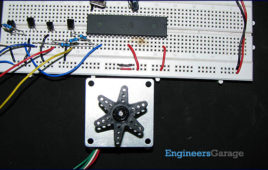
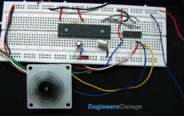
Stepper motor is one of the commonly used motors for precise angular movement. The advantage of using a stepper motor is that the angular position of the motor [[wysiwyg_imageupload::]]shaft can be controlled without any feedback mechanism. Stepper motors are widely used in industrial and commercial applications. They are also commonly used as in drive systems of autonomous robots.This article explains the unipolar stepper motor interfacing with AT89C51 microcontroller. The microcontroller is programmed to rotate the stepper in wave drive and half drive stepping modes. For basic concepts and working of a stepper motor, refer the article on Stepper Motors. A Unipolar Stepper Motor is rotated by energizing the stator coils in a sequence. In unipolar stepper, the direction of current in stator coils is not required to be controlled by the driving circuit. Just applying the voltage signals across the motor coils or motor leads in a sequence is sufficient to drive the motor.
Stepper Motor : Basics, Types and Working
A stepper motor or a step motor is a brushless, synchronous motor which divides a full rotation into a number of steps. Unlike a brushless DC motor which rotates continuously when a fixed DC voltage is applied to it, a step motor rotates in discrete step angles.The stepper motor can be controlled with or without feedback. Stepper motors work on the principle of electromagnetism. There is a soft iron or magnetic rotor shaft surrounded by the electromagnetic stators. The rotor and stator have poles which may be teethed or not depending upon the type of stepper. When the stators are energized the rotor moves to align itself along with the stator or moves to have a minimum gap with the stator.
How to interface Servo Motor with AVR Microcontroller (ATmega16)- (Part 21/46)

Servo motors find huge applications in industries in the field of automation, control & robotics. The servo motors are well known for their precise control and work [[wysiwyg_imageupload::]]on the principle of servo mechanism. The servo motors can be made to run at precise angle using PWM. The PWM (pulse width modulation) is the basic working principle behind a servo motor (For more details about PWM refer Phase correct PWM mode). This article explores the interfacing of servo motor with ATmega16. Also to know more about servo mechanism see Interfacing Servo Motor with 8051. There are different types of servos available in the market. This article bounds its scope to interfacing a commonly available servo, widely used by hobbyist with ATmega16. Such a servo consists of three wires positive supply, ground and a control signal. Unlike other motors, Servo motors don’t require any driver. When a PWM signal is applied to its control pin the, the shaft rotates to a specific angle depending on the duty cycle of the pulse.
Servo Motor control through Keypad using 8051 Microcontroller (AT89C51)- (Part 20/45)
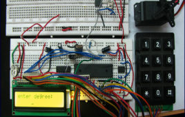
The basic operations of servo motor control have been discussed in interfacing servo with 8051. This project allows the servo motor to move to an angle specified [[wysiwyg_imageupload::]]by the user. The pulse train required to rotate the servo is produced by AT89C51 microcontroller. The desired angle of rotation is provided through a 4×3 keypad interfaced to the microcontroller. A 16×2 LCD is also connected with the microcontroller to display the angle of rotation entered by the user. For basic operations and control of servo motor, refer interfacing servo with 8051. The first pin of port P1 (P1^0) of AT89C51 microcontroller is set as the output pin to provide control signal to the servo motor. Ports P0 and P2 are used to interface keypad and data pins of LCD, respectively. Ports P1^3, P1^4 and P1^5 are connected to RS, RW and EN pins of LCD, respectively. Before connecting to the control wire of servo, the output from the microcontroller (P1^0) is fed through a comparator IC (LM324) so that the signal is protected from any loss due to overloading.