NAND Gate is created by applying NOT operation to an AND gate. Hence, the outputs of this gate are opposite to that of AND gate when the inputs are kept [[wysiwyg_imageupload::]]same. NOT gate is a logic element whose output stage is always the complement of the input stage means when you supply logic 1 we will logic 0 and vice versa. The operation of AND gate is such that output of gate is binary 1 if and only if all input are binary 1. If any of the input is binary 0 we will receive output as binary 0. OR gate is another basic logic gate like AND gate it as two input and one output. The operation of gate is such that output of gate is binary 1 if any of the input is binary low and we will receive logic zero only when both the inputs are low.
NAND Gate as SR Flip Flop
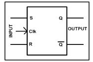
SR Flip flops are the basic element of the sequential circuit. Flip flop is a digital circuit capable of storing single bit of binary data. They can store either of the two [[wysiwyg_imageupload::]]stable state that is binary zero or one. If flip flop is set to one particular state it will store that until power is switched off or until you have changed the state. This means that flip flop remembers the state it was previously set and memorizes the data provided to it. Here we have designed the SR flip flop with the use of NAND gate. SR flip flop has two inputs S and R. S is used to set the flip flop and R is used to reset the flip flop and two outputs Q and Q(NOT) in this one is complement of another. When flip flop is storing 1 we can said that it is set and while reset it is storing 0.
Luggage Security Alarm
While travelling in public transport such as buses or trains, people usually carry expensive belongings and are quite insecure about their safety. Even though after [[wysiwyg_imageupload::]]locking the luggage thoroughly, there is always a worry about it.To solve this problem here is a simple circuit based on NAND gate. When somebody tries to steal the luggage, the circuit will give a warning alarm. An audio visual indication can also be provided by connecting it to the relay.This project circuit can also be used in home to prevent the attempt of burglary as when somebody tries to open the door, the loop breaks and the alarm. The project is built around CD4011 with components like LDR, variable resistor, capacitor, transistor and relay.. It generates a warning beep when somebody attempts to open the locker.
Electronic alarm for cash box, lockers
The project presented can be used as a smart circuit for the cash box that thwarts any theft attempt by activating an emergency alarm. This can also be used to [[wysiwyg_imageupload::]]trigger any external burglar alarm by connecting a relay to the output of the circuit. The circuit is built around a NAND gate IC in which all gates are used as an inverter. The circuit is based on the concept of Light Dependant Register (LDR) whose resistance varies with the intensity of light falling on it. This small circuit can also be installed in a locker system where if somebody tries to open the locker, the light will fall on the LDR and the circuit will start sounding with the help of buzzer connected to the relay. A switch is also provided so that the circuit can be switched off when not in use to save the battery power.
Automatic Night Light Control
Automatic night light control system needs no manual operation for switching ON and OFF when there is need of light. It detects itself whether there is need for light or not. When darkness rises to a certain value then automatically light is switched ON and when there is other source of light i.e. day time, the light gets OFF. In the project we use light detecting resistor as a light sensor & a NAND gate for detection of high level or low level of voltage to energize the RELAY coil which is used to interface the control circuit with the external light source.
Astable mode by NAND gate
Astable Multivibrators are a type of “free running oscillator” that have no permanent “Meta” or “Steady” state but are continuously changing from one state [[wysiwyg_imageupload::]]”LOW” to the other state “HIGH” and then back again to its original state.This continuous switching action from “HIGH” to “LOW” and “LOW” to “HIGH” produces a continuous square wave output which has been shown in this electronics project. The circuit based project uses IC 7400, which has four inbuilt NAND gates. The two NAND gates along with a capacitor(C) and resistor(R) are connected as shown in the figure. Suppose that initially the output from the second gate U2 is high, the input must therefore be low, as will be the output from the first NAND gate U1. The capacitor now charges up at a rate determined by the time constant of R and C. Read on more to find out how the circuit is made and how it works.
Monostable mode of 555 timer using NAND gate
555 timer IC is commonly used in monostable mode to generate a pulse every time a trigger is given. The project described here uses NAND gate for [[wysiwyg_imageupload::]]monostable operation and thereby avoiding the need of 555 timer.The circuit in the project uses IC 7400, which has four inbuilt NAND gates. Here we have used the first and second NAND gate of the IC 7400. Suppose, initially the trigger input T is High at a logic level “1” so that the output from first gate (U1) is Low at logic level “0”. The resistor, R will cause the capacitor, C to charge or discharge. The output from the second NAND gate (U2), which is connected as an inverting NOT gate is also fed back to the input of U1,which is at logic level “1”. Since both junction V1 and the output of U1 are both at logic “0” no current flows in the capacitor C and this results in the circuit being Stable and will remain in this state until the trigger input T changes.


