
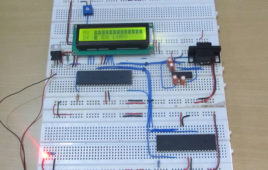
The Serial Peripheral Interface (SPI) is a high speed, synchronous, serial communication standard. This communication protocol is basically a Master – Slave implementation where the master device controls the clock based on which the slave devices operate. The master communicates with a slave or a number of slaves in a system through the SPI bus. The SPI bus requires a minimum of three wires including SDO (Serial Data Out), SDI (Serial Data Input) and SCK (Serial Clock). Since it is a master controller system the SDO is also called MOSI (Master Output Slave Input) and the SDI is also called MISO (Master Input Slave Output). The SPI is a full-duplex high speed communication protocol. The master and slave can transmit and receive data at the same time. The master is the device which generates clock for all these data transmissions. Read PIC microcontroller tutorial based on PIC18F4550 microcontrollers in which one of the microcontroller acts as a slave transmitter and the other acts as master receiver. With the help of an LCD, this particular project demonstrates the complete data transfer between a master and slave when both the master and slave are transmitting and receiving the data at the same time.
How to use PIC18F4550 as a SPI Slave Transmitter- (Part 25/25)
The Serial Peripheral Interface (SPI) is a high speed, synchronous, serial communication standard. This communication protocol is basically a Master Slaveimplementation where the master device controls the clock based on which the slave devices operates. The master can communicates with one or more slave in the system through SPI bus. The SPI bus requires a minimum of three wires i.e. a SDO (Serial Data Out), SDI (Serial Data Input) and SCK (Serial Clock). Since it is a master controller system the SDO is also called MOSI (Master Output Slave Input) and the SDI is also called MISO (Master Input Slave Output).The SPI is a full-duplex high speed communication protocol. The master and slave can transmit and receive data at the same time. The master generates clock for all these data transmissions.The SPI is special because it is simple and easy to implement in the hardware. The article explores the SPI hardware module of the PIC18F4550 microcontroller. This project will help in better understanding of the SPI protocol in detail.
How to interface Servo Motor with PIC Microcontroller- (Part 21/25)

Servo systems use the error sensing negative feedback method to provide precise angular motion. Servo Motors are used where precise control on [[wysiwyg_imageupload::]]angular motion is needed. Servo motors are widely used in the field of Robotics to design robotic arms, palms, legs and so on. They are also used in RC toys like RC helicopter, airplanes and cars.The interfacing of servo motor using PIC microcontroller has been explained here. Readers are advised to go through the article on Servo Motors to learn basic mechanism and control of servo motor.A Servo motor has three wire terminals : two of these wires are to provide ground and positive supply to the Servo DC motor, while the third wire is for the control signal. These wires of a servo motor are color coded. The servo motor can be driven only when PWM (pulse width modulated) signals are provided to the control terminal. The total pulse duration for a typical servo motor should be of 20 milliseconds. The on-time duration of the control signal varies from 1ms to 2ms. This on-time variation provides angular variation from 0 to 180 degree. Also refer Servo motor control using 8051.