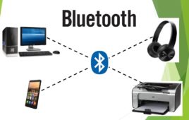
Handheld devices like a cell phone, palmtop and laptop were rapidly becoming an integral part of our daily lives. In most cases, these devices do not have compatible data communication interfaces, or, if they do, the interface requires cumbersome cable connections and configuration procedures. Isn’t it absolutely fantastic to connect your PC to share music, data and calendar info without using any wires? Or to wirelessly access phone numbers on your PDA from your cell phone.
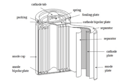
What battery chemistries are used in electric vehicles?
Despite a higher price tag initially, electric vehicles (EVs) tend to offer significant savings over time. The environmental benefits aside, which are noteworthy, EVs typically cost half as much to maintain and repair as gas-powered vehicles — and they’re growing in popularity. Unlike conventional vehicles, EVs don’t have internal combustion (IC) engines. Instead of gasoline,…
What are the different types of EV charging connectors?

Battery electric vehicles (EVs) have showcased rapidly growing sales figures over the last several years. There are several reasons to consider an EV aside from saving on gasoline. The prominent one, of course, is the environment. EVs have no tailpipe emissions, and research shows that they’re responsible for lower levels of greenhouse gases (GHGs) than…
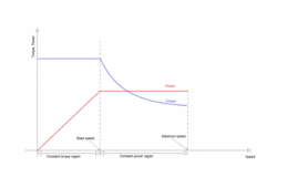
What types of motors are used in electric vehicles?
Conventional vehicles that rely on internal combustion engines (ICE) could become a rarity in the next couple of decades. Electric vehicles (EVs) are growing in popularity, replacing petrol-driven transportation faster than expected. Despite a higher initial price tag, EVs typically offer savings over time. The environmental benefits aside (which are noteworthy), EVs cost half as…
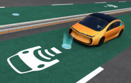
What is Wireless Electric Vehicle Charging System (WEVCS)?
Electric vehicles are shaping the future of mobility and, as nearly all electric vehicles are turning out to be more economical compared to any gasoline car, there has been a shift in the buying trend of automobiles. It is expected that there will be more electric cars on the road than fossil fuel cars by…
The top computer vision tools for embedded systems

Computer vision is reaching new levels, far beyond basic image processing. This is thanks to the integration of artificial intelligence. AI now enables computers and systems to derive meaningful information from digital images that can be used in advanced industries. Currently, one of the most common applications is in security and surveillance. A computer vision…
Practical application of hardware filters with real-life examples
In previous articles (including here, here, and here), we discussed the different types of filters available, including examples. If you’ve followed along, you should have an understanding of the frequency components (i.e., attenuating high frequencies when using a low pass filter and the passing frequencies for a high pass filter). You should also be aware…
What are the top tools for developing embedded software?

The embedded software or firmware is the brain of an embedded device. However, this type of software works differently than the conventional ones on PCs or mobile devices — which are generic and work identically on such operating systems. PC software runs without directly accessing the underlying hardware. The purpose of embedded software works in…
What are the top development boards for AI and ML?
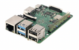
Machine learning (ML) and artificial intelligence (AI) are no longer limited to high-end servers or cloud platforms. Thanks to new developments in integrated circuits (IC) and software technology, it’s possible to implement ML algorithms and deep learning neural networks on tiny controllers and microcomputers. And these embedded devices installed at edges must no longer rely…
How to build an Arduino lie detector based on electrodermal activity
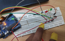
A polygraph is an instrument that records physiological indicators like pulse rate, blood pressure, and electrodermal activity of a human subject under questioning by an operator. It’s commonly referred to as a lie-detector test because it’s designed to assess whether a person is telling the truth. Industry-standard polygraph equipment is said to be 80 to…
What to expect from microcontrollers in 2023
Microcontrollers are the workhorse behind most embedded systems. They serve as a compact integrated circuit (IC) designed to govern a specific operation in an embedded system. The programmable firmware used in these tiny computers is ideal for and fits well into several applications. Microcontrollers are neither too specific, like application-specific integrated circuits (ASICs), nor too…
The top EDA tools for circuit and PCB design in 2023
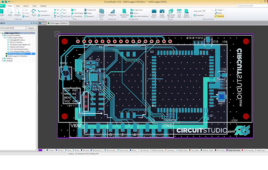
Electronics manufacturing is possible thanks to electronic design automation (EDA) software. EDA has computerized and automated several processes in product design and production. While some tools focus on circuit design and simulation, others target design analysis, verification, and manufacturing preparations. Each tool provides a unique package optimized for electrical and electronics engineers. Although no tool…
What are the sensors used in self-driving cars?

Automotive engineers have already developed semi-autonomous vehicles. Fully self-driving vehicles are not far from reality. According to recent research, autonomous driving (AD) could create $300 billion to $400 billion in revenue by 2035. The self-driving car not only showcases how advanced technology is, but it’s also a subject of controversy. There are valid concerns about…
India’s first drone traffic management system — Skye UTM

India launched its first indigenous drone traffic management system in February 2023. The system is Skye UTM, developed by Skye Air Mobility. Skye Air Mobility is a leading drone delivery company in India. It has been streamlining drone delivery services in multiple logistics solutions, including e-commerce, Agri-commodity, quick commerce, healthcare, etc. UTM, which stands for…
The top 3D-printed robotic arms for 2023

Previously, we discussed open-source 3D printable humanoid robot projects. Now, we’ll cover the top 3D printable robotic arms. A robotic arm is a pick-and-place robot typically used in manufacturing assembly lines. They’re also used for CNC, laser engraving, and 3D printing. The robots are designed to repeat specific tasks with the highest accuracy and precision. Servos electronically…
The top modeling software for 3D printing in 2022

Additive manufacturing or 3D printing is more affordable than it’s ever been. Although some hobbyists buy a printer for crafts and to experiment with, it’s also an excellent engineering tool for innovative electronics or robotic projects. Typically, printers offer complimentary 3D models or free downloads that are ideal to start with. Eventually, you’ll likely want to…
How drones are serving next-generation logistics

E-commerce is no longer novel. Online shopping delivered to one’s doorstep has become a typical millennial lifestyle. The backbone of the e-commerce industry is the shipping and logistics sector. However, of the biggest challenges for shipping companies is the timely delivery of orders at the lowest possible cost. Digitalization has helped by providing real-time tracking…
What is LiDAR and how does it work?
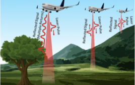
LiDAR is an acronym for light detection and ranging, an optical technology for sensing distance. Early attempts to measure distance by light beams were first made in the ’30s, and airborne LiDAR became more commonly used in the ’60s, with geospatial measurements beginning in the ’80s. As the technology evolved, LiDAR’s uses continued to expand.…
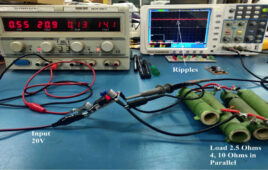
How do dc-dc converters work?
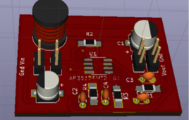
A DC power supply is used in almost all of devices where a regulated voltage is required. A DC converter implements the process of DC conversion. There are two types of DC converters: Buck converter- Steps down the input source voltage Boost converter – Steps up the input source voltage Conversion topology Linear regulator –…
What is Lightweight Internet Protocol (LwIP)?

Connecting embedded microcontrollers to the internet is a crucial task in modern applications. The embedded controllers, particularly in consumer devices and wearables, now essentially require ping online. This is more important as the devices are getting smarter. Connecting to the internet is not just crucial but a hefty task as well. The typical TCP/IP stack…