Vishay Intertechnology, Inc. recently announced that the company’s facility in Borgaro Torinese, Italy, has received a research results R&D grant for its WATT4FRED project from the European Union and the Regional Government of Piedmont. The project will focus on the development of a new high-voltage FRED Pt diode family featuring advanced technologies for the automotive…
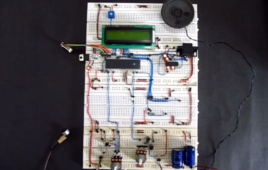
How To Use PIC Microcontroller For Voice Input And Output- (Part 23/25)
Microcontrollers are purely digital devices which work on logic0 and logic1 voltages; still they are widely used for analog signal processing. There are specialized signal processors chips available which are custom made for particular applications; however a general purpose microcontroller is more than enough for small kind of signal processing applications like audio signal input and output. The microcontroller can read the analog input voltage by sampling it and converting it to their digital values. The Analog to Digital Converter (ADC) available in almost all the microcontrollers help in this task. A timer can be used to generate the sampling time period. The sampled values can then read and modify by the microcontroller. The modified signal is then output by the microcontroller in the form of Pulse Width Modulated (PWM) waves. Most of the microcontrollers have the PWM module which helps them in generating analog voltage output at an external device.
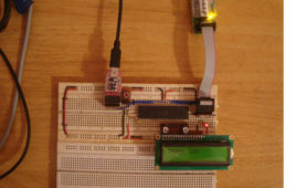
How To Use SPM To load Application from EEPROM – (Part 34/46)
In any microcontroller the Boot-Loader is the first code which executes before the application code does. The major function of the Boot-Loader is to load the application code into the flash memory of the microcontroller and execute it. In AVR microcontroller the Self Programming Mode (SPM) helps the Boot-Loader to load a particular application from where the application binary is stored.The Boot-Loader may receive the code binary from other memory chips, SD-cards or through the serial port of the microcontroller in case of serial programming. It is then with the help of the SPM that the microcontroller write the binary code into the application flash section. In this particular project the operation of a Boot-Loader code using the SPM is demonstrated by re-writing flash memory with the code binary which has already been flashed into the built-in EEPROM of the ATMEGA16. The hardware used in this project includes ATMEGA16 as microcontroller, USBASP as the programmer and the software used are AVR STUDIO4 as IDE and AVR-BURNO-MAT as the burner software.
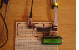
How to Use SPM for Flash to Flash Programming – (Part 33/46)
The Self Programming Mode (SPM) is a feature which enables a microcontroller to program its own flash memory. Using the SPM a microcontroller can program itself with an SPM code. The SPM is commonly used with the microcontroller Boot-Loader codes which help to program the microcontroller serially. In AVR microcontroller the SPM is available only for the code running in the BLS of the flash memory. With the help of the SPM a code in BLS can rewrite the application flash memory entirely or a part of it. It can even rewrite its own code in the BLS section. The SPM is a key factor of the Boot-Loader code since the major function of the Boot-Loader is to load an application code into the application flash section. The Boot-Loader may receive the code binary from other memory chips, SD-cards or through the serial port of the microcontroller in case of serial programming.
How to Initialize Peripherals from Boot Loader Section- (Part 32/46)
In almost all the microcontroller codes the peripheral initialization functions like uart initialization, spi initialization are written along with the different application codes. These initialization functions are actually repetitions of the original initialization functions. The same is the case with the external hardware initialization like LCD initialization, GSM modem initialization etc. Suppose the case in which the application codes required are stored in a memory chip or SD memory card so that there is an option to select between the applications. If all the application codes have the same functions for peripheral and external hardware initialization that will simply increase the size of the code only and the size of the memory required to store the codes. It will take too much time for the Boot-Loader to load such a large size application and there will be flash memory shortage issues due to the large code size. These issues can be solved by doing the initialization of the peripherals and the external hardware in the code running from the BLS itself.
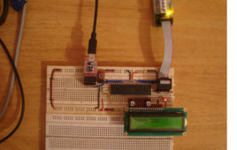
How to Program in Boot Loader Section- (Part 31/46)
In the AVR microcontroller the flash memory is divided into two parts, namely Application Section and Boot Loader Section. A code can be programmed into either the Application Section or the Boot loader Section (BLS). The code programmed into the Application section runs normally and is used for common applications, whereas the code running in the BLS is provided with some special features. The code running in the BLS section can execute Self Programing Mode (SPM) instructions which are blocked for the code running in the Application section. Using SPM instructions the code from the BLS can rewrite the code in the application section or the code in the BLS itself. The BLS section is normally used for storing the Boot-loader code for the microcontroller. The Boot-Loader code can be used for initializing the peripherals in the microcontroller, initialize the devices connected to the microcontroller, select the application to load and execute from a storage medium, load the selected application to the application section, jump to the application section and execute the application.
How to interface RFID with PIC18F4550 Microcontroller- (Part 15/25)
RFID (Radio Frequency Identification and Detection) is widely used everywhere from highly secured defense laboratories to school attendance system. By [[wysiwyg_imageupload::]]employing RFID, much secured entry systems can be developed without incurring huge costs. These are the reasons of excessive use of RFID technology. In this article, interfacing of an RFID reader module has been explained with PIC18F4550. The USART interrupt, an internal PIC interrupt, has also been explained. (For more details on USART, refer PIC EUSART)As explained earlier (refer RFID interfacing with 8051 & with AVR), an RFID module consists of an RFID Reader, a line converter (usually MAX232) and a COM port. The line converter of this module converts the TTL logic voltage of RFID Reader to RS232 logic. Therefore, to convert the voltage level from such an RFID module, another MAX232 is used to interface it with a microcontroller. One can also use an RFID Reader directly to interface with the controller, thus avoiding the need of voltage level converters. Here both the MAX232s have been eliminated from the circuit and RFID reader is directly connected with the PIC microcontroller.


