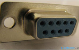
Serial interfacing is one of the most common protocols to make two electronic gadgets communicate. In such interfacings, the data is sent sequentially and bit bybit. RS232 is one sub type of serial interfacing that was introduced in the year 1932. Available in 9 pin and 25 pin configurations, RS 232 pins allow data exchanges at the maximum of 256kbps. Some well known applications of these connectors include linking modems to computers and other micro controller based UART electronic gadgets. Of course, such an interfacing would require different types of connectors; in this case, RS232 connectors are used. The Insight covers a conventional 9 pin female RS232 connector. Let’s find out the outer and inner details of it.
RS232: Basics, implementation and specification

Simple analog communication over the telephone wires to the typical USB cables for data exchange, we surely have come a long way in the field of communication. RS232 was the first milestone reached in this journey. It was a standard for electromechanical typewriters and modems for digital data exchange introduced in 1962 by the Radio Sector of EIA. It made the data exchange more reliable over analog channel. The standard defined voltage levels that made it immune to noise disturbances and reduced the error in data exchange.As the technology was growing many electronic devices were being developed during this time like computers, printers, test instrument etc. There came a time where manufacturers felt the need to exchange information between these electronic devices. For example data exchange between a computer and a printer or two computers. But there was no standard or method to accomplish this task. RS232 was the only available standard at the time which was used for data exchange. So, they thought of adopting this standard in electronic devices for digital data exchange.
RS232 (Serial Cable)
Before Universal Serial Bus (USB) in computers RS232 was used as a standard port for communication between different devices like printers, mouse, modems and all other type of computer peripherals and the computer. In terms of definition, RS232 can be defined as point to point communication between the Data Terminal Equipment (DTE) and Data…
Interfacing ADC0808 with Serial port (RS232) using interrupt clock from 8051 microcontroller (AT89C51)- (Part 27/45)
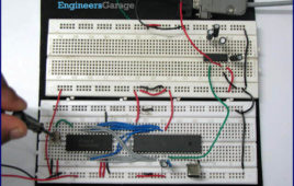
In many applications data collected from multiple sensors is transmitted to PC for display or further analysis. The conversion of data from analog to digital form is done using an ADC. The digital data from the ADC is transferred to the computer using serial port. This circuit demonstrates the principle and operation of interfacing an ADC0808 with serial port of PC using the microcontroller AT89C51. The circuit is divided into three parts: ADC, controller and serial port. This circuit can be used as an intermediate circuit in many applications.ADC0808 which is an 8-bit resolution ADC has eight input channels i.e., it can take a maximum of eight analog inputs. The circuit uses the first analog input pin to take the analog input signals from the preset. To provide clock input to the ADC, Timer0 is used in interrupt enabled mode to generate a clock of frequency 500 KHz. To enable the Timer0 in interrupt enable mode, the register IE is loaded with the value 0x82. Every time the timer completes the counting, pin P1.2 toggles its state.
How to interface computer’s Serial Port (RS232) with 8051 microcontroller (AT89C51)- (Part 21/45)

Several devices collect data from sensors and need to send it to another unit, like a computer, for further processing. Data transfer/communication is generally [[wysiwyg_imageupload::]]done in two ways: parallel and serial. In the parallel mode, data transfer is fast and uses more number of lines. This mode is good for short range data transfer.Serial communication on the other hand, uses only one or two data lines to transfer data and is generally used for long distance communication. In serial communication the data is sent as one bit at a time. This article describes the interfacing of 8051 microcontroller (AT89C51) with a computer via serial port, RS232. Serial communication is commonly used in applications such as industrial automation systems, scientific analysis and certain consumer products. The microcontroller AT89C51 has an inbuilt UART for carrying out serial communication. The serial communication is done in the asynchronous mode. A serial port, like other PC ports, is a physical interface to establish data transfer between computer and an external hardware or device. This transfer, through serial port, takes place bit by bit.
Interfacing ADC0804 with Serial port (RS232) using 8051 micocontroller (AT89C51)- (Part 23/45)
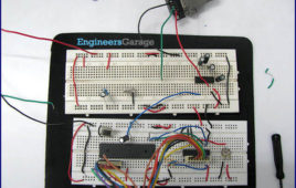
This circuit demonstrates the principle and operation of collecting data from ADC0804 and sending it to PC via serial communication using 8051 microcontroller [[wysiwyg_imageupload::]](AT89C51). The circuit is divided into three parts: ADC, Controller and Serial Port. This circuit can be used as an intermediate in many applications.ADC0804 which is an 8-bit resolution ADC has only one input channel connected to variable resistance (preset) to give the analog input. In place of preset, analog input from a sensor can also be used. The output pins of the ADC are connected to port P1 of the microcontroller. Write (WR) pin 3 is connected to P2.0 i.e. pin 21 of controller. Read (RD) pin 2 is connected to P2.1 i.e. pin 22 of controller. Interrupt (INTR) pin 5 is connected to P2.2 i.e. pin 23 of controller. Read more to find out how this 8051based project works and what aspects of coding does it cover.
How to interface AVR microcontroller with PC using USART (RS232 protocol)- (Part 13/46)

This article covers data transmission using 8 bit USART. The readers should have a basic understanding of serial communication and how to receive the serial [[wysiwyg_imageupload::]]data output. More details on these topics are available on Serial communication using AVR Microcontroller USART. The registers of USART system are already explained in previous article. Before transmitting the data, it must be stored in UDR register. The HyperTerminal software is used to show received data. A sequential process can be followed to transmit the data to COM port of computer. Continue reading to find out how interfacing and transmission through 8 bit USART can be done with the help of AVR microcontroller.