
A kind of Read Only Memory (ROM), which can be written and erased by means of electrically programming the data, is called Electrically Erasable Programmable Read Only Memory (EEPROM). Once programmed the data it will remain in the memory for a very long time even if there is no power available. The EEPROM comes in small sized chips which can be interfaced with microcontrollers in a system. Most of the microcontrollers have built-in EEPROM with reasonable memory size so that for small kind of applications an extra memory chip can be avoided. A microcontroller uses the EEPROM memory to store its data like sensor value, or a particular count or image data for a long period of time uses the EEPROM memory. The EEPROM memory is also used to save the data before the system switches itself off so that the same data can be retained next time when the system is turned on.
Interfacing ADC0808 with Serial port (RS232) using interrupt clock from 8051 microcontroller (AT89C51)- (Part 27/45)
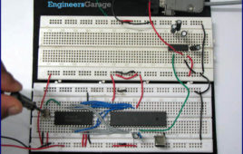
In many applications data collected from multiple sensors is transmitted to PC for display or further analysis. The conversion of data from analog to digital form is done using an ADC. The digital data from the ADC is transferred to the computer using serial port. This circuit demonstrates the principle and operation of interfacing an ADC0808 with serial port of PC using the microcontroller AT89C51. The circuit is divided into three parts: ADC, controller and serial port. This circuit can be used as an intermediate circuit in many applications.ADC0808 which is an 8-bit resolution ADC has eight input channels i.e., it can take a maximum of eight analog inputs. The circuit uses the first analog input pin to take the analog input signals from the preset. To provide clock input to the ADC, Timer0 is used in interrupt enabled mode to generate a clock of frequency 500 KHz. To enable the Timer0 in interrupt enable mode, the register IE is loaded with the value 0x82. Every time the timer completes the counting, pin P1.2 toggles its state.
How to interface computer’s Serial Port (RS232) with 8051 microcontroller (AT89C51)- (Part 21/45)

Several devices collect data from sensors and need to send it to another unit, like a computer, for further processing. Data transfer/communication is generally [[wysiwyg_imageupload::]]done in two ways: parallel and serial. In the parallel mode, data transfer is fast and uses more number of lines. This mode is good for short range data transfer.Serial communication on the other hand, uses only one or two data lines to transfer data and is generally used for long distance communication. In serial communication the data is sent as one bit at a time. This article describes the interfacing of 8051 microcontroller (AT89C51) with a computer via serial port, RS232. Serial communication is commonly used in applications such as industrial automation systems, scientific analysis and certain consumer products. The microcontroller AT89C51 has an inbuilt UART for carrying out serial communication. The serial communication is done in the asynchronous mode. A serial port, like other PC ports, is a physical interface to establish data transfer between computer and an external hardware or device. This transfer, through serial port, takes place bit by bit.
Interfacing ADC0804 with Serial port (RS232) using 8051 micocontroller (AT89C51)- (Part 23/45)
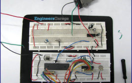
This circuit demonstrates the principle and operation of collecting data from ADC0804 and sending it to PC via serial communication using 8051 microcontroller [[wysiwyg_imageupload::]](AT89C51). The circuit is divided into three parts: ADC, Controller and Serial Port. This circuit can be used as an intermediate in many applications.ADC0804 which is an 8-bit resolution ADC has only one input channel connected to variable resistance (preset) to give the analog input. In place of preset, analog input from a sensor can also be used. The output pins of the ADC are connected to port P1 of the microcontroller. Write (WR) pin 3 is connected to P2.0 i.e. pin 21 of controller. Read (RD) pin 2 is connected to P2.1 i.e. pin 22 of controller. Interrupt (INTR) pin 5 is connected to P2.2 i.e. pin 23 of controller. Read more to find out how this 8051based project works and what aspects of coding does it cover.