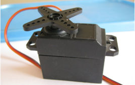
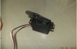
The article discusses designing a servo motor angle controller using the IC NE555. The servo motor used here for an experiment is an 11-gram micro servo motor with the following specifications. Rotational range 160o Operating voltage …
Controlling Servo Motor using Freeduino
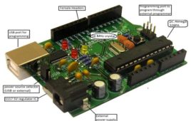
Servo is a special type of motor which converts electric signals in to shaft positions. Servos can be broadly classified as Industrial servos and Hobby grade [[wysiwyg_imageupload::]]servos.Industrial servos are generally heavy duty high power AC or DC servos widely used for precise robotic arms.Hobby grade servos are widely used in RC Hobbies like RC Plane, Cars Helicopters, Multirotors, Boats, hover craft, etc.They are mostly used to control the control surfaces (RC Planes) or for thrust vectoring mechanisms (hovercraft, boats, multirotors) or for steering mechanisms (RC Cars).Hobby grade servos are further classified as micro, standard, giant based on the torque they can provide, however their working principal is just the same.Based on speed of operation they are classified as Analog or Digital servos, Digital servos provide greater speed but consume more power.Speed of a servo motor is defined as time taken for shaft to move from 00 to 600 after the application of signal. In this article we will be using an ARDUINO clone board viz. FREEDUINO.
Unmanned Aerial Vehicle
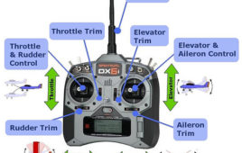
In the last few years the interest in Unmanned Aerial Vehicles (UAVs) and their use for an ever increasing range of applications has grown tremendously. This [[wysiwyg_imageupload::]]type of aircrafts can be controlled remotely or programmed to fly in an autonomous way. They have been used for different types of applications as individual entities, both in military and civil tasks. Research related to this type of systems is being undertaken in many areas going from the design of more efficient aircraft aimed at specific applications, to the development of improved control electronics that provide for better autonomous behaviors, to optimized path planning strategies, or to opening new application domains. Currently, a whole new field of research is opening up in the area of coordinating UAV teams to cooperatively perform different missions. This field is still in its infancy and many exciting new approaches are being explored for different applications. Examples of these are works related to trajectory planning in UAV teams, real time target tracking, and many others.
Servo Motor Control Using 555 Timer IC
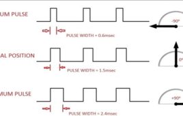
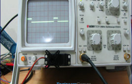
Normal DC motors just require power supply(+V and GND) and are controlled by switching it ON/OFF or by varying the amount of power supplied to it but in case of servo motors we generally need a microcontroller to control them since it needs a special signal along with the normal power supply(+V,GND and SIG). This circuit will show how to control a servo without using a microcontroller. The circuit uses a 555 Timer IC which is very cheap when compared to a microcontroller and also which doesn’t require programming. The 555 IC is configured in Astable Mode to generate the “Special Signal” for the servo motor to work. First let us understand that signal. Here the special signal is nothing but a Pulse Width Modulated signal usually with a frequency of 50Hz (i.e. a Time Period of 20msec) or 25Hz (Time Period 40msec).
Cell phone operated Robotic Arm
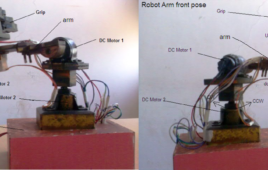
This is also picked and place type robotic application. But this has a unique feature that it is controlled from cell phone. It’s all the movements are controlled from any cell phone. That means you can control this robot from anywhere in the world where GSM / CDMA network service is available. Isn’t it very interesting??!!!!????…..The robot has built in GSM / CDMA cell phone that receives signals from other cell phone. One has to call the number of the cell phone (that is inside robot) from his cell phone to activate it. Then by pressing different keys from 0 – 9 form the phone he can control the movements of the robot. It is 4-axis robotic arm. It’s all four motions are controlled by 2 DC gear motors and 2 servo motors.Let us start with mechanical structure of robot.
Insight – How Servo Motor works
Servo Motors are DC Motors with a servo mechanism to provide a precise angular motion. Pulse width modulation (PWM) technique is used to set the angle of rotation. Generally RC servo motors have a rotation limit of 900 to 1800 but servos with high rotation angles are also available.A DC motor and the potentiometer which is used to provide feedback to the electronic circuitry. It is connected with the DC motor with the help of gear assembly. As soon as the motor starts rotating the potentiometer also starts rotating and the output of potentiometer i.e. voltage across the middle terminal changes which acts as the feedback signal to indicate the degree of rotation of the motor.
How to interface Servo Motor with PIC Microcontroller- (Part 21/25)
Servo systems use the error sensing negative feedback method to provide precise angular motion. Servo Motors are used where precise control on [[wysiwyg_imageupload::]]angular motion is needed. Servo motors are widely used in the field of Robotics to design robotic arms, palms, legs and so on. They are also used in RC toys like RC helicopter, airplanes and cars.The interfacing of servo motor using PIC microcontroller has been explained here. Readers are advised to go through the article on Servo Motors to learn basic mechanism and control of servo motor.A Servo motor has three wire terminals : two of these wires are to provide ground and positive supply to the Servo DC motor, while the third wire is for the control signal. These wires of a servo motor are color coded. The servo motor can be driven only when PWM (pulse width modulated) signals are provided to the control terminal. The total pulse duration for a typical servo motor should be of 20 milliseconds. The on-time duration of the control signal varies from 1ms to 2ms. This on-time variation provides angular variation from 0 to 180 degree. Also refer Servo motor control using 8051.
How to interface Servo Motor with AVR Microcontroller (ATmega16)- (Part 21/46)
Servo motors find huge applications in industries in the field of automation, control & robotics. The servo motors are well known for their precise control and work [[wysiwyg_imageupload::]]on the principle of servo mechanism. The servo motors can be made to run at precise angle using PWM. The PWM (pulse width modulation) is the basic working principle behind a servo motor (For more details about PWM refer Phase correct PWM mode). This article explores the interfacing of servo motor with ATmega16. Also to know more about servo mechanism see Interfacing Servo Motor with 8051. There are different types of servos available in the market. This article bounds its scope to interfacing a commonly available servo, widely used by hobbyist with ATmega16. Such a servo consists of three wires positive supply, ground and a control signal. Unlike other motors, Servo motors don’t require any driver. When a PWM signal is applied to its control pin the, the shaft rotates to a specific angle depending on the duty cycle of the pulse.
Servo Motor control through Keypad using 8051 Microcontroller (AT89C51)- (Part 20/45)
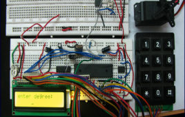
The basic operations of servo motor control have been discussed in interfacing servo with 8051. This project allows the servo motor to move to an angle specified [[wysiwyg_imageupload::]]by the user. The pulse train required to rotate the servo is produced by AT89C51 microcontroller. The desired angle of rotation is provided through a 4×3 keypad interfaced to the microcontroller. A 16×2 LCD is also connected with the microcontroller to display the angle of rotation entered by the user. For basic operations and control of servo motor, refer interfacing servo with 8051. The first pin of port P1 (P1^0) of AT89C51 microcontroller is set as the output pin to provide control signal to the servo motor. Ports P0 and P2 are used to interface keypad and data pins of LCD, respectively. Ports P1^3, P1^4 and P1^5 are connected to RS, RW and EN pins of LCD, respectively. Before connecting to the control wire of servo, the output from the microcontroller (P1^0) is fed through a comparator IC (LM324) so that the signal is protected from any loss due to overloading.
How to interface Servo Motor with 8051 Microcontroller (AT89C51)- (Part 19/45)
This project demonstrates the operation of a servo motor. The control signals for the rotation of the motor are provided by 8051 microcontroller (AT89C51). Here, [[wysiwyg_imageupload::]]the servo arm is rotated by 5° from the previous position, starting from 0 °as initial position. As the servo reaches a limit, the arm comes back to the initial position (0°). For basic concepts and know-how of a servo motor, refer to the article Servo Motor.The servo motor is controlled by feeding pulse width modulated (PWM) signal at the control wire of the servo motor. In addition a 4.8V (ideally 5V) DC supply is provided to the red lead of the servo. The black lead of the servo is connected to Ground. The first pin of port P1 (P1^0) of AT89C51 microcontroller is set as the output pin to provide control signal to the servo motor. Before connecting to the control wire of servo, the output from the microcontroller is fed through a comparator IC (LM324) so that the signal is protected from any loss due to overloading.
Servo Motor : Basics and Working
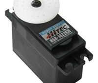
Servo refers to an error sensing feedback control which is used to correct the performance of a system. Servo or RC Servo motors are DC motors equipped with a servo mechanism for precise control of angular position. They are used in robotic arms and legs, sensor scanners and in RC toys like RC helicopter, airplanes and cars.The servo motor can be moved to a desired angular position by sending PWM (pulse width modulated) signals on the control wire. The typical specifications of servo motors are torque, speed, weight, dimensions, motor type and bearing type.
Interfacing Servo Motor with Arduino MEGA-2560
Servo motor is widely used by many engineering students and hobbyists in various applications. One major application is Robotics. Servo motor is used because it is easy to operate (PWM technique). It can maintain 90%of its rated torque at high speed. Sometimes a servo can provide up to twice its rated torque for short duration. Also, a servo operation is vibration-less and is free of resonance issues. This article is about interfacing a servo motor with Arduino Mega series board.


