This circuit will scan the sound vibration present near the vicinity and convert them into audible sound or beeps to alert you. Many of us live alone in home and always fear that somebody is walking in the corridor especially in nights. So, to solve this, just install this circuit in your sit outs, car porch and many other places in your house. So when ever any person walk around microphone it will pick up the sound and will give you beep sound to alert you. The circuit comprises of Operational amplifier ?A741 which is used as a sensitive voltage comparator. The main advantage of this circuit is it can detect vibration up to a distance of 3 meters. Keep on reading to find out how the circuit is assembled and how it is put to work.
How to Add Sound to Raspberry Pi Game Pad- (Part 37/38)
The gamepad is a simple circuit built on a breadboard with few buttons, LEDs and a resistor array. There are eight general purpose IO pins on the 13*2 pin connectors of the Raspberrypi board and among them four pins has been selected as input and then remaining four pins as output. The input pins are connected to push button and are pulled down using 1K resistors. The output pins are connected to the LEDs through another set of 1K resistors. For this project the Raspberry pi board is loaded with Ubuntu and is remotely accessed using VNC. To access the pins that coming out of the Broadcom controller the C library “bcm2835” has been downloaded and installed. This article focuses on how to add sound to a game that is coded to be played with a Raspberry pi gamepad.
Sound Operated Switch
Detailed here is a circuit which will switch ON the light by just listening your clap sound. Another advantage of this circuit is that you cannot get any electrical [[wysiwyg_imageupload::]]shock as we did not have to use any mechanical switch.The circuit is based on two IC :operational amplifier LM741 and JK flip-flop based CD 4027.An op-amp produces an output voltage that is hundreds of thousand times larger than the voltage difference between its input terminals .CD4027 is the master slave JK flip flop IC which work in toggle mode. Here, this IC can be used to change the state by signal applied to one or more control inputs and will have one or two outputs. CD4027 has four inputs namely J, K, Set and Reset and it contain two output namely Q and Q bar(Q not).
Insight – How Stethoscope Works
One of the few compulsory gadgets that every doctor carries is the Stethoscope. A sophisticated assembly constructed out of steel and plastic, stethoscope is an age-old source to diagnose cardiac problems. Popularly known as “Doctor’s Weapon”, stethoscopes have seen innumerous changes in their structure and working since their invention in 1824. Models that can be tuned with a smart phone (yes, really!) have already hit the market. Peculiarly, almost every type of stethoscope has found its space in the vast world of medical experts. There’s one for a cardiac for example, a different one for a pediatrician and yet another for a physicist. This Insight covers one of the most popular types of stethoscopes: Littmann Stethoscopes, which you may recognize as the serpentine devices hanging around doctors in movies. These stethoscopes are one of the oldest species and are still recommended for their precise results.
Sound Operated LED
The LED starts glowing as intensity of sound varies. This project can be used to measure the intensity of sound present in the room as sound intensity increase [[wysiwyg_imageupload::]]number of LED glows also increases. Circuit is based on LM324 which is 14 pin IC consisting of 4 independent operational amplifiers. The output voltage of LM324 is many times higher than the voltage difference between the input terminals of an op amp.LM324 IC is used as a comparator and when input voltage rises above the reference voltage, output is attained. When no noise or audio signals are present in the room, output voltage on pin 1 is zero as voltage on pin 2 is lower than that at pin 3. Since, the IC works as comparator, less voltage on pin 2 in comparison to pin 3 will not make the LED glow. Let’s find out the working of this interesting project.
Sound Generation using 555
The task of this circuit is to give a frequency output which lies in the audible range of a human being, i.e in between 20 and 20,000Hz. Sound is generated in this [[wysiwyg_imageupload::]]circuit by using two 555 timer IC’s. The other components required in this project, along with the two ICs are few resistors and capacitors, one diode, 12 Volts DC power supply, and a speaker. In this project both the ICs are wired as astable multivibrator. Both the 555 timers operate at different frequency ranges. IC1 works at a frequency of about 20Hz as a slow astable multivibrator with duty cycle of 50%. IC2 operates at a frequency of 600Hz as a fast astable multivibrator. Keep on reading to find out how the circuit is constructed and how it works.
Insight – How Speaker works
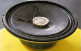
Technically we can define speaker, as a component which converts the electrical signals into the equivalent air vibrations to make audible sound. To understand the working of a speaker, we first need to understand the concept of sound. A sound is nothing but vibrations in air particles. When a sound source generates a sound, it generally makes a vibration in its surrounding air particles which finally reaches to our eardrum. Sound is characterized by the parameters like frequency, speed, fluctuation, pressure, etc. The speaker works on the same concept. The speaker works on the same concept. It produces vibrations in air particles in order to generate a sound. Let’s have a look to its outside formation
How to generate sound using 8051 microcontroller (AT89C51)- (Part 18/45)
Sound is a function of frequency. This concept has been used to generate sound from the microcontroller. Different types of sounds can be produced by varying [[wysiwyg_imageupload::]]the frequency.Frequencies are generated by using Timer1 of microcontroller. Timer is used to produce exact delays and by toggling the output pin we can generate the desired frequencies. These frequencies are then fed to a particular pin (here Pin 0 of port1) which is connected to speaker. The output can be heard on the speaker. By combining the different frequencies we can generate different tones and alarms.
Sound operated display on LCD using 8051 microcontroller
This is an interesting idea in which a message is displayed on an LCD screen whenever a sound is produced. The message remains on LCD for a short duration of [[wysiwyg_imageupload::]]time and then disappears. This topic demonstrates the interfacing of a sound operated circuit and LCD display with the 8051 microcontroller (AT89C51). The circuit can be used to display welcome message at entrance; or warning messages at public places. It can also be used to aid communication for deaf and dumb people.The circuit consists of four major modules, namely, a sound sensor, an amplifying circuit, a control circuit and a display module. A switching circuit is also employed after the amplifier.Any sound, say clap, is detected by a microphone (condenser mic) which acts as the sound sensor. This mic is connected to a two stage transistor amplifier. The mic output is thus amplified to a suitable level so that it can be detected at the TTL logic.


