
Although a smaller shape, switches are essentially crucial for any device and hence, a design engineer should consider so many technical things related with a switch, while choosing a switch. Some of the few important terms that are taken care while configuring a switch are operating force, stroke, bounce time, various resistances, dielectric strength, power ratings etc.Alteration in these mentioned configurations affects the structure and working of switch in every possible manner. Hence, from a hardware designer to an installer, switch configuration plays an important part for any electrical device.The most common specifications found in the datasheet of switches are explained below.
Switch : Basics, Types, Structure
In our day-to-day lives, how often do we encounter switches? Switches can be seen everywhere. For electronic and electrical system, they act as a physical interface to the real world. Be it a key of a keyboard or mobile or be it a knob on an electrical appliance or be it a miniature button used on the PCBs of embedded systems or be it a circuit breaker used on the power lines- all these are switches. We are in continuous interaction with switches without bothering about the manner it functions behind the scene?Switches are of different types, of different specifications and are selected and used in a particular application according to specific requirements. Subsequent sections will discuss the switches in detail.
Insight – How Rocker Switch Works
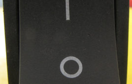
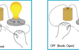
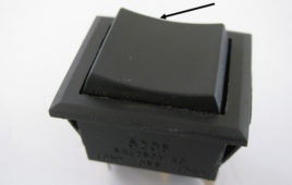
Rocker switches arepopular among gadgets like computer printers, UPS, SMPS etc. Used solely for the purpose of shifting device operation from ON to OFF, rocker switches can be engaged or disengaged with a small force. Rocker switches are available in various types and sizes depending on the power requirements of the device they are used in. They often come with a light source mounted beneath the actuator to indicate the ON state.Named on their motion like a rocker chair or a cradle, rocker switches present an interesting structure and internal assembly.Let’s find out the internal intricacies that enable the operation of the switch.
Insight – How Piano Switch works
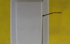
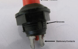
The best place to find a piano switch is the nearest switchboard one can find. They are available in different sizes, shapes depending on the application and number of switches can be placed on a single switch board. Installing and changing the switch is also quite easy and anyone having a basic know-how about electricity can use these switches.How do these switches handle high electrical voltage inputs? How are the interior configurations of the switch designed? Why they don’t stop in between their motion? Let’s find out some interesting information about these switches in this article
Insight – How Rotary Switch Works
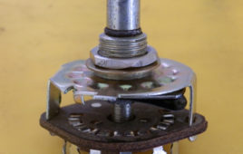
When it comes to selecting one mode (or state) from multiple modes (or states) to operate a device , rotary switches turn up as one of the most exemplified type of switch. Some well known applications of rotary switches include speed control in fans, speed control in conveyer belts, selecting time, frequency on the CRO, step control of AC/DC drives and electro-hydraulic valves. These switches can be thoroughly customized depending on applications. But what makes these mechanical switches able to deliver multiple types of outputs? What structure they have to accommodate so many output stages? How are they able to avoid the size and cost trade-off? This article will explore answers to many more interesting questions.
Insight – How Momentary Rocker Switch Works
Momentary rocker switches is a type of rocker switches which come back to their position as soon as the force is removed. They are spring loaded and resemble a rocker chair in their to and fro motion. Not just limited to doorbells, momentary rocker switches are widely used in medical machinery, testing equipments, defense, aerospace etc. As the name suggests they give momentary output.Inside the simple looking switch lies an interesting piece of mechanical engineering. What forces the switch to come back to its original state? Is it because of some magnetic force or does it requires an extra power source? How the different mechanical components are arranged to make the switch work?
Insight – How Push Button Switch Works
Ever imagined how quickly the horn of your vehicle responds? Not even a second or two, just push the button and there comes the sound. You put your hand off the button and it’s back to silent mode. An instant response of these horns is due to what we call “push -button switches”. Push button switches are those which can be made to work with the force of a finger or two. Not only vehicles but camera, lifts and several other common and uncommon interactions with machines/gadgets involve push button switches applications. But what makes this switch so user friendly? What makes it respond only for the time it is pressed no longer or shorter? How the contacts inside this switch work?
Insight – How Slide Switch works
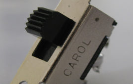
Slide switches are one of the most common switches used in electrical devices. Compact sized and operable with only a finger, slide switches are important as their absence can render the device useless in absence of the capability to switch ON and OFF without having to pull the mains cord. It is uncanny to list all the applications where slide switch is used. From electrical chimneys to hand blender in the kitchen, from lamp to the toy car in the living room, slide switches are almost omnipresent.We are used to see switches and use it as a black box. But have you ever thought how does a slider of few centimeters control big machines? What happens inside the switch when it makes and breaks the connection? Is it an assembly of several even smaller components? Why does it keep on working irrespective of the environmental conditions? Let’s find out the internal as well as external features of the switch that make it work.
Insight – How DIP Switch works
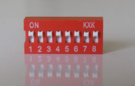
DIP switch can be defined as an array of simple two terminal On-Off electromechanical switches (Single Pole Single Throw) that are commonly used in electricity operations. The word DIP is an acronym for Dual In-line Package which means that the electrical contacts are in two rows. DIP switches are surface mountable and are used in those applications where multiple numbers of switches are involved in output generation. For instance, in a universal remote control, the DIP switch is used to set the frequency according to the device that is being operated. On a computer motherboard, DIP switches help in optimizing the clock speed and configuration settings according to the type of processor mounted.
Insight – How Reed Switch works
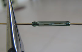
Magnets have a natural tendency to attract many things. Though not perceived as a real force, but it does attract human attention when a force acting invisibly draws things to itself. By harnessing this power, humans have made wonderful inventions like the electromagnet and discover lossless conduction phenomenon like superconductivity. Among these many inventions, was the application of magnetism to switch from ON state to OFF and vice-versa in precision devices. One such switching device, which works not by the principles of electricity, but magnetism, is the Reed Switch.
Insight – How MCB works
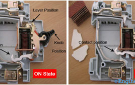
MCBs or Miniature Circuit Breakers are electromechanical devices which protect an electrical circuit from an overcurrent. The overcurrent, in an electrical circuit, may result from short circuit, overload or faulty design. An MCB is a better alternative to a Fuse since it does not require replacement once an overload is detected. Unlike fuse, an MCB can be easily reset and thus offers improved operational safety and greater convenience without incurring large operating cost. The principal of operation is simple. An MCB functions by interrupting the continuity of electrical flow through the circuit once a fault is detected. In simple terms MCB is a switch which automatically turns off when the current flowing through it passes the maximum allowable limit. Generally MCB are designed to protect against over current and over temperature faults (over heating).
Touch Switch Circuit using 555 Timer
In this project, when power is supplied to the touch switch circuit, the devices connected to it remain ideal as voltage at pin2 is zero. When the switch is turned ON, trigger pin (pin2) receives trigger signal. The output pin (pin 3) receives a high output due to which transistor gets turned ON. Simultaneously relay…
Wireless Industrial Switching System with Real Time Feedback

The wireless industrial switching system can be used to switch on or off four devices that are connected to the system. When these devices are switched on or off the status is shown on the control panel. This status shown is not a mere reflection of which switch has been pressed on the control…
Touch Switch for On/Off High Voltage Electrical Equipments
Touch switch with a 555 timer has been built long before. The basic idea is the 555 timer should be configured in monostable mode and the TRIGGER terminal of the 555 timer is left open as TOUCH lead. The discrepancy in using the design is switching both ON and OFF intentionally i.e. once the lead…
Insight – How Toggle Switch works
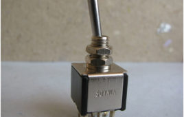
SPDT stands for Single Pole Double Throw. It comes with 6 pin. It has 2 states ON and ON. For instance if we have two devices a red LED and a blue LED then SPDT switch will turn ON red in one position and blue in other position. By making different connections of the pins the two ON states can be made of same polarity or opposite polarity. Hence, it will switch ON a different device in each position. Hence, it is also known as changeover switch. This switch has found applications in industry, etc.
Insight – How Tactile Switch works
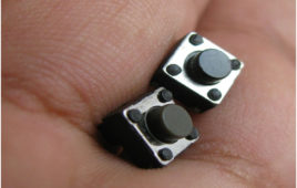
Tactile switches are most often found in control panels of monitors, televisions, mobiles, radios, etc. They are widely used in industry for different purposes. They come with various number of pins as per the requirement. A tactile switch has only two states ON and OFF. Here 4 pin tactile switch is discussed.Inside the switch we can see there is a hat like thing. Actually it’s the button that we tap. The button looks very similar to a hat. At the bottom of the button there is a pointing arrow and below it lies a conducting plate. The pins are attached below the plate.
Insight – How 8 Pin DPDT Switch works

DPDT stands for double pole double throw switch. By using this we can change the polarity of the applied voltage. It is used in situations where we need different outputs. It has 3 states ON, OFF, ON. The difference between the two ON is that the polarity of both the states is opposite with respect to each other.That’s the reason why it can drive the dc motor in both directions. It can also switch an ac motor but it can’t change the direction of the motor. Since, ac motor will run in same direction irrespective of the polarity therefore, it can only be used for switching ON and OFF for an ac motor but not for changing its direction.
Insight – How Relay Switch works
Relay is one of the most important electromechanical devices highly used in industrial application specifically in automation. A relay is used for electronic to electrical interfacing i.e. it is used to switch on or off electrical circuits operating at high AC voltage using a low DC control voltage.Relays are available in different operating voltages like 6V, 12V, 24V etc. A relay generally has two parts a coil which operates at the rated DC voltage and a mechanically movable switch. The electronic and electrical circuits are electrically isolated but magnetically connected to each other, hence any fault on either side does not affects the other side.
Touch switch using monostable mode of 555 timer IC
This project demonstrates the principle and operation of application based on touch sensor. The circuit is divided into three parts: Input, 555 timer and output. A [[wysiwyg_imageupload::]]touch plate is used for the input and output can be seen across an LED or a buzzer. Some application of the circuit include touch based blinking lights, touch buzzer, touch switch etc.This circuit can be used in the following applications: 1. To detect stray voltages produced by mains or to detect electrostatics build up in a room.2. To make touch buzzers. 3. To implement touch switches like for a bell.
How to take input with PIC18F4550 Microcontroller- (Part 2/25)

Any microcontroller based system typically has an input and a corresponding output. Taking simple output with a PIC microcontroller has been explained inLED [[wysiwyg_imageupload::]]blinking with PIC18F4550. This article explains how to provide an input to the controller and get a corresponding output using PIC18F4550. PIC18F4550 has a total of 35 I/O (input-output) pins which are distributed among 5 Ports. Each Port of a PIC microcontroller corresponds to three 8-bit registers (TRIS, PORT & LAT) which should be configured to use the Port for general I/O purpose. For more details, refer LED blinking using PIC.To configure a particular port/pin as input, the corresponding TRIS register/TRIS bit should be set to high (1). For output, the relevant TRIS register/bit should be set to low (0). Read on to know more about PIC micro controller and get a step by step approach to take input with PIC. A must learn for every budding PIC enthusiast.