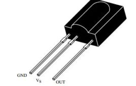
Today we are controlling many appliances with the help of remote like AC, TV or music system. It often happen that remote stops working due to any reason (lowbattery or any button of remote becomes faulty). Therefore circuit describes below help you to test your remote to identify that appliance (TV, AC etc) has problem or your remote is not responding. Advantage of circuit- Based on single sensor and hence circuit consumes very less power. Almost every remote can be tested with the help of this circuit as operating frequency of sensor is 38 KHz. High immunity against ambient light. With little modification in the circuit you can use it to control your home appliances with remote.
Polarity cum Continuity Tester
This simple polarity cum continuity tester indicates the polarity of many components like diodes, LED including Zener diode and infrared LED. This can also be used to check the above components are good or bad before mounting them on the PCB. Many a times, it happens that people are unable to identify the polarity of the component which leads to wrong soldering of components that damages the components or it may damage the whole circuit. This circuit can also be used as continuity tester, to test the continuity of the circuit. The circuit is made with the help of two transistor configured as astable multivibrator. Outputs of both the transistors are out of phase with each other meaning that if output of one transistor is high then output of another transistor will be low or vice versa.
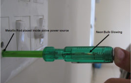
Insight – How electrical Line Tester screwdriver works
Testers are one of the simplest solutions, used to test current and voltage continuity in any circuit. Indispensible for any electrician, the testers are very simple and interesting devices. This article will explore the internal structure of one such commonly used circuit tester.The user is required to be on the floor while using the tester so that he can serve as ground when current flows. In order to test the live wire, the user’s body must be in contact with the metal cap on the top of the screwdriver when the tester is put in contact with the wire. This completes a genuine electrical circuit and the bulb will light up once the tester senses voltage.
Transistor Tester Circuit Diagram
This project is a transistor analyzer, suitable for testing both NPN and PNP transistors. Its circuit is simple as compared to other transistor testerswhich is [[wysiwyg_imageupload::]]useful for both technicians and students. It can be easily accumulated on a general purpose PCB. Basic electronic components like resistors, LED’s, diode and NE5555 are used for developing this circuit. Using this circuit, many of the faults can be checked like transistor is in good condition or not, is it opened or shorted, and so on. NE555: As the name suggests, NE 555 is multivibrator IC which is popularly known to work in three modes: astable, monostable and bistable. Also, circuit can work through a battery for a longer duration, without compromising the working abilities or disturbing the normal functioning of the passive components attached.
Remote Control Tester
The Remote Control Tester designed here uses the Monostable Mode operation of a 555 Timer. The circuit can be used to check the working of any remote control. If the remote control is working then it produces a beep sound at the buzzer and the LED glows. And if it is not working they are…


