A watchdog timer is an internal or external timer that monitors a microcontroller’s program to ensure the application remains operative without failure. It serves as a safety feature in critical applications by monitoring the microcontroller’s output signal. The watchdog can operate in two modes: Timeout mode – the timer establishes the microcontroller is not working properly if it…
Timers & 8051 Timer Programming

What is a Timer A timer is a clock that controls the sequence of an event while counting in fixed intervals of time. It is used for producing precise time delay. Secondly, it can be used to repeat or initiate an action after/at a known period of time. This feature is very commonly used in…
How to Use Timer in Raspberry Pi -(Part 20/38)
In this project the Raspberrypi board is loaded with Ubuntu and is remotely accessed using VNC. The Raspberrypi board is also connected to the internet. There are 26 connectors which can be taken out from the connector port of the Raspberrypi board. All the connector pins are taken out using 13*2 pin female connectors and at the other end of their wire 26 pin Burg stick male connectors are attached. The Burg stick male connectors allow each pin out from the Raspberrypi board to be plugged into the holes of a breadboard. To access the pins that coming out of the Broadcom controller of the Raspberrypi board using C language, a C library is available called “bcm2835” which has been downloaded and installed. A signal is sent for the purpose of notifying the process about something that required immediate attention. Different signals are used to notify different events and the signals are differentiated by their signal numbers.
Digital Clock with Alarm using Timer/Counter

This entire project is divided in to 2 parts, the first part demonstrates the software implementation of the digital clock on Atmega16 and the second part demonstrates the hardware implementation of digital clock on WSN-EK development kit (ATMEGA324PA). In this project we have implemented a digital clock with the help of 16 bit timer. Thus this project illustrates the basic use of timer and its interrupts. The timer will interrupt Microcontroller after every 1s and perform the given ISR (Interrupt Service Routine).
Multipurpose Timer With Musical Alarm
The circuit is built around two IC namely CD4060 and UM66 with few more components. IC CD4060 is 14 stage ripple carry binary counter, divider and an oscillator. Its built in oscillator is main feature of this IC that’s why it can be used in numerous application like flasher, clock generator in timer circuits. UM66…
Pre Set Off Timer
Pre set off timer automatically turns off the devices after set time. Many of us have habit to fell asleep while watching TV or while listening music and the device [[wysiwyg_imageupload::]]remains switched on for the whole night. For such problems, you can use this simple circuit which will turn off the device automatically after the set time and will also engage an alarm. You can also vary the set time according to your requirement. This can also be used by students who are preparing for competitive exams they can use it as alarm clock. This simple circuit is built around four transistors. Connect the power supply and press the push to on switch momentarily to on the device. Keep on reading to find out how this circuit is assembled and how it works.
Automatic Power OFF timer for CD player
Many people have habits to sleep while listening to music. So, device remains switched ON for the long durations which lead to wastage of energy. To avoid [[wysiwyg_imageupload::]]this, we have described a simple circuit which automatically become OFF after the set time. In this circuit, device become on while sensing the darkness , hence whenever you switch off the light, CD player connected to relay becomes ON and after set time it becomes OFF so there is no need to off the device as it turn off automatically so there is no wastage of electricity also.The circuit is built around the CD4060,LDR and few more components. IC CD4060 is a 14 stage ripple carry binary counter, divider and an oscillator. Its built in oscillator is main feature of this IC that’s why it can be used in numerous application like flasher, clock generator in timer circuits. LDR is a light dependent resistor its property depends upon the intensity of light falling on it.
NE 555 Timer based Automatic Headlight
Automatic headlamp is very useful for miners as it eliminate the need to manually switch the headlamp ON and OFF while entering into the mines where light is [[wysiwyg_imageupload::]]not sufficient. The circuit described below works as a human eye to outside light levels and independently turns on and off the lights when needed .It hence offers both safety and convenience. This circuit is very helpful when you are entering into a tunnel at twilight or sunlight even in foggy and rainy condition. For example when you enter into a dark tunnel you will not have to search for headlight switch it will automatically turn on after sensing the poor quality of light and when you come out from tunnel it will turn off automatically.The headlamp circuit is based on NE555, which is widely known to generate accurate timing pulses. Being a multivibrator IC, NE555 works in monostable and astable mode.
Timer Circuit using IC CD 4060
Several times we forget to switch off the gas, electric oven, stove or motor while watching TV or taking on the phone or while talking to a friend in your [[wysiwyg_imageupload::]]neighborhood. To solve this problem we have described a circuit below which gives an alarm after the preset time interval selected by you. In this you can select 7 different time intervals with the help of a rotary switch. Therefore after a preset interval of time it will give a loud alarm and reminds you that you have to off your machine or gas.The timer circuit is built around the CD4060 which is 14 stage ripple carry binary counter, divider and an oscillator. Its built in oscillator is main feature of this IC that’s why it can be used in numerous application like flasher, clock generator in timer circuits.
Electronic Timer Circuit
Nowadays students are required to answer a set of question in a given time of 15 minutes, 30 minutes or an hour. Hence the circuit describe below can be used [[wysiwyg_imageupload::]]by the student as a clock while they are preparing for the competitive exams.It will give them audio visual sound after the pre set time interval. In our circuit it is 15 minutes hence it will give an alarm after every 15 minutes. The timer could be programmed for other periods as well. By calibrating the variable resistor by some hit and trial method, you can vary the time period. We have also provided a reset switch so that you can reset it when you are required to start it again. The circuit is built around CD4060 and few more components. IC CD4060 is 14 stage ripple carry binary counter, divider and an oscillator.
Three Stage Sequential Timer for DC motor control
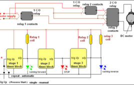
In most of the industrial processes it is required to rotate DC (or AC) motor forward and reverse for desired time. First motor rotates forward (clockwise) for some time (say 2 – 3 min) then it stops for some time. Again it rotates reverse (anticlockwise) for some time and rests. This process repeats every time when gets triggeredSequential timer is widely used circuit in industries because in most of the industries all the processes are of chain reaction type. That means one process ends and it triggers next. The last process triggers first process when it ends. And thus the cycle continues. These sequence timers are micro controller based multi-functional and programmable.But here we have a sequential timer using simple IC555. So let us see how it is done
Touch Switch Circuit using 555 Timer
In this project, when power is supplied to the touch switch circuit, the devices connected to it remain ideal as voltage at pin2 is zero. When the switch is turned ON, trigger pin (pin2) receives trigger signal. The output pin (pin 3) receives a high output due to which transistor gets turned ON. Simultaneously relay…
Night Lamp with Timer for Stairs
This circuit is based on the phenomenon of Push-ON and Auto-OFF. This means that when the circuit is switched ON, it will remain ON for specific period of Night Lamp with Timer for Stairs>time and then it will turn OFF automatically. Again to switch ON the circuit the user has to push the button ON…
How to configure Watchdog Timers of AVR Microcontroller (ATmega16)- (Part 15/46)
Some high end applications require multiple or critical calculations to be done by the microcontroller. This may lead to cases when the controller enters intowrong or infinite loops. As a result of this, the system either hangs up or gets crashed. The solution to overcome these situations is to automatically reset the system whenever such a situation arises.The Watchdog Timer is a hardware or software generated timer interrupt which reboots/resets the system in the situations mentioned above. The watchdog timers are also used in cases when you intentionally require resetting the system without any physical interference.The AVR microcontroller has an in-built watchdog timer. This article explains the working of watchdog timer in ATmega16. The Watchdog Timer is a special timer which can be enabled in any section of the code and when enabled it ensures that a certain number of instructions execute within a pre-defined time frame. This time frame or the time delay can be configured/set using the registers of the watchdog timer.
Countdown timer using 8051 microcontroller (AT89C51)

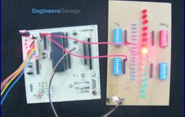
A countdown timer is a down counter that counts from a specified time to 00:00. It is used in many devices such as washing machine, televisions, microwave [[wysiwyg_imageupload::]]ovens, etc. This countdown timer has three states: the running state where it counts down, the pause state where it displays the paused time and the reset state to set the countdown. The countdown is displayed on a set of four seven segment displays using the 8051 microcontroller (AT89C51). A buzzer sounds when the countdown gets over. The countdown timer keeps the track of time the same way as a simple digital clock does. The control options are provided by means of tactile switches which are active low. As soon as the Vcc supply is provided to the circuit, the timer goes in reset mode with 00:00 display state on seven segments. The segment to be set can then be selected in cyclic order each time S2 is pressed. After selecting the desired segment, its value can be changed by using S3.
Waveform Generation using AVR Microcontroller (Atmega16) Timers- (Part 16/46)

At times we come across applications or situations wherein we need to generate square waves with the microcontroller. The square wave can be generated by [[wysiwyg_imageupload::]]programming a pin which toggles between 0 and 1 with a certain time delay. Alternatively, the inbuilt feature of AVR timers can be used in square wave generation. The advantage of using AVR timers in wave form generation is that the output pin toggles automatically when the timer condition are fulfilled. This article focuses on usage of AVR timer for simple square wave generation. It is better to use CTC mode instead of Normal mode because in CTC mode, frequency can be easily adjusted. ?When the Timer is triggered, register TCNTn counts the value constantly as timer started. Each timer has an OCRn (Output Compare Register), which is continuously compared with TCNTn register. In CTC mode whenever match occurs, OCFn (Output Compare Flag) will set to 1. If continuous wave form generation is required, OCFn must be reset again. Alternatively, if OCIEn (Output Compare interrupt) and Global interrupt flags in SREG are set, OCFn will reset automatically after interrupt execution.
Phase Correct PWM (Pulse Width Modulation) Mode of AVR microcontroller Timer- (Part 17/46)
Pulse Width Modulation is well known technique for controlling power electronics devices like SCR, IGBT etc. PWM is also used in motor speed controlling.[[wysiwyg_imageupload::]] Square wave generation by using AVR timers is explained in previous article. The AVR timers have feature of PWM wave generation as well .This article describes PWM generation capability of AVR timers. There are four in-built PWM channels in ATmega16. The PWM outputs are received on pins OC0, OC1A, OC1B and OC2. Readers can refer the previous article which gives explanation of these pins. The Phase correct PWM mode can be selected by assigning bits WGM0[1:0]=01. This mode is based on dual slope operation. In dual slope operation, TCNTn counts from bottom value to maximum value and maximum value to bottom value. The OCRn register compares the value with the TCNTn register constantly during up-counting and down-counting. On compare match PWM output pin (OCn) behaves according to inverting or non-inverting mode which can be selected by programming of COMn [1:0] bits.
How to use fast PWM (Pulse Width Modulation) Mode of AVR microcontroller Timer- (Part 18/46)
This article is in continuation of PWM generation using AVR timer. In the previous article, PWM generation using Phase correct PWM mode is described. [[wysiwyg_imageupload::]]However, there are some applications like DAC, power regulation and rectification etc. which require high frequency PWM wave. The PWM generation using Fast PWM mode is suitable for such applications. This article focuses on Fast PWM mode of AVR Timer. The Fast PWM mode is based on single-slope operation. In single slope operation, the register TCNTn counts from bottom value to maximum value and its value resets to zero. The counting starts again from bottom. The register OCRn compares the value with the TCNTn register constantly. If the timer is configured in non-inverting mode, PWM output pin (OCn) goes low when the value of the above two registers matches. The OCn pin becomes high when the TCNTn register reaches at bottom value. In inverting mode OCn pin behaves opposite to non-inverting mode. For timer 0 fast PWM mode, following table shows the functionality of COM 0[1:0] bits.
Johnson Counter: How to use IC CD4033
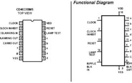
CD4033 is a Johnson counter IC commonly used in digital display. It has a 5 stage Johnson decade counter with decoder which convert the Johnson code to a 7 [[wysiwyg_imageupload::]]segment decoded output. Means it will convert the input into numeric display which can be seen on 7 segment display or with the help of LED’s.Advantage of this IC is it can be operated at high voltage of 20V. But is highly sensitive, can detect emf present in the atmosphere and is sensitive to static charge also. When you touch your finger at its input terminal its counter get started therefore care should be taken while using it. It can be used in various application like in 7 segment decimal display circuit, in clocks, timer etc. To understand its working first have a look on its pin diagram. Read more to find out how it is can be used in various applications.