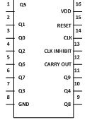
The project described below is a small model of traffic light which we daily see in our life on street. With this circuit you can control two way traffics. There will be lights on both sides, like there is red light on one side and green light will be present aautomatically on another side. It will also have yellow light to alert the passengers or drivers that now there signal are going to open.CD4017 is a 16 pin CMOS decade counter/ Divider. It take clock signal from the clock input and turn on the 10 output in sequence, each time when it receives clock input pulses.4072 is a dual 4 input OR gate. Output of OR gate goes high when any of the input goes high and if all input is low then output is also low7432 is a quad 2 input OR gate. In this also output goes high when any of the input is high and goes low when all inputs are low. 7432 contains 4 individual OR gate on single IC.
Traffic light signal using 555 timer in astable mode
This project describes the functioning of the traffic light system, which are commonly used on the streets. In this circuit 555 timer is used to produce a clock [[wysiwyg_imageupload::]]pulses, which are used by a counter to produce the required output. Mentioned below are a few interesting facts about this circuit:· The 555 timer is used in its astable mode.· Besides 555 IC, a 4017 IC which is CMOS decade counter is also used in this circuit.· A bypass capacitor too is used in the circuit. Read more to find out how the circuit can be constructed and how it works.
Two Way Traffic Light
The project described below is a small model of traffic light which we daily see in our life on street. With this circuit you can control two way traffics. There will be lights on both sides, like there is red light on one side and green light will be present aautomatically on another side. It will also have yellow light to alert the passengers or drivers that now there signal are going to open.CD4017 is a 16 pin CMOS decade counter/ Divider. It take clock signal from the clock input and turn on the 10 output in sequence, each time when it receives clock input pulses.4072 is a dual 4 input OR gate. Output of OR gate goes high when any of the input goes high and if all input is low then output is also low7432 is a quad 2 input OR gate. In this also output goes high when any of the input is high and goes low when all inputs are low. 7432 contains 4 individual OR gate on single IC.


