
Children like to watch cartoons movies or any other their favourite show on the television and do not pay attention on their studies even at the time of examination. So to keep eye on children we have design a parental control device. When the children in your home hold the remote of the television to on the TV or want to change channel and press any button of the remote then a loud sound would be generated by the device. And these will let you know that your child has tried to switch on the TV. The main advantage of these circuit is that you can easily do your work without any trouble as it produces loud noise so you can hear the noise while working in the kitchen or while sitting in the nearby room.
Remote Controlled Toy Car
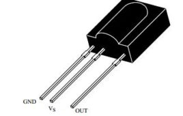
Remote control toy car circuit can be used to on and off the motor of the toy car with the help of your remote. You can use any remote of TV, AC, DVD player to control the movement of motors.This low cost circuit is based on the CD4017 counter IC which receives trigger pulse from IR sensor and switch ON the relay. And with the relay, motors are connected which also get switched ON. Upon receiving the second pulse motor gets turned OFF.You can control your toy car upto 5 meters range. This is a simple circuit based on infrared sensor IC TSOP1738. TSOP1738 contains photo detector and preamplifier in one package. It is three terminal device having pin 1 configured for ground, pin 2 for power supply and pin 3 as output. Keep on reading to find out how the circuit works.
Remote Tester Circuit
Today we are controlling many appliances with the help of remote like AC, TV or music system. It often happen that remote stops working due to any reason (lowbattery or any button of remote becomes faulty). Therefore circuit describes below help you to test your remote to identify that appliance (TV, AC etc) has problem or your remote is not responding. Advantage of circuit- Based on single sensor and hence circuit consumes very less power. Almost every remote can be tested with the help of this circuit as operating frequency of sensor is 38 KHz. High immunity against ambient light. With little modification in the circuit you can use it to control your home appliances with remote.
TSOP 1738: How to test TSOP1738
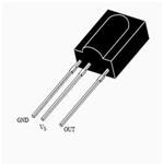
I am designing a circuit which can be controlled by TV or AC remote. For that I have purchase TSOP1738 with few more components from market. And I assemble my circuit carefully, then also I am not getting the desire output. I again rechecked my assembled circuit with the circuit diagram and I don’t find…
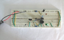
Operating Device using TSOP1738 based IR transmitter and receiver & relay

Operating an electrical/electronic device through wireless communication is very commonly required and seems very interesting. The circuit of the project [[wysiwyg_imageupload::]]described here can operate such appliances. A few salient features of the circuit are shown below:1. The circuit mainly comprises of a transmitter and a receiver component.2. Whenever a signal is received by the receiver, it activates a switch which in turn turns the appliance on.3. In this project, the transmitter component of the circuit is basically an Infrared (IR) Led which is configured to emit rays at a frequency of 38 kHz. For this purpose, NE 555 timer is used in astable mode.
Parental Control
Children like to watch cartoons movies or any other their favourite show on the television and do not pay attention on their studies even at the time of examination. So to keep eye on children we have design a parental control device. When the children in your home hold the remote of the television to on the TV or want to change channel and press any button of the remote then a loud sound would be generated by the device. And these will let you know that your child has tried to switch on the TV. The main advantage of these circuit is that you can easily do your work without any trouble as it produces loud noise so you can hear the noise while working in the kitchen or while sitting in the nearby room.