Obviously you might have seen so many temperature controller and indicator applications using different microcontrollers, micro-processors or other controlling devices. But this is the actual application of temperature controller that controls speed of DC fan as temperature varies. It is not a simple ON-OFF type controller that switches fan ON / OFF when temperature increases / decreases certain limit. But it is a type of controller that continuously varies speed of DC fan as temperature increases / decreases. That is a demo of actual industrial application.
Circuit
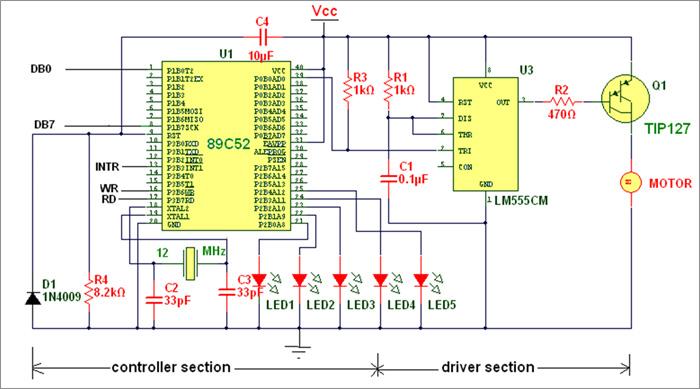
Controller and driver section
Software program
Video
Project Source Code
###
#include<reg51.h>
#include<string.h>
sbit wr = P3^6;
sbit rd = P3^7;
sbit op = P0^0;
sbit eoc = P3^3;
unsigned char data d;
unsigned int d1=3,d2=7;
void delay(int a)
{
int k;
TL0 = 0x26;
TH0 = 0xFC;
TR0 = 1;
for(k=0;k<a;k++)
{
while(TF0==0);
TF0 = 0;
TL0 = 0x26;
TH0 = 0xFC;
}
TR0 = 0;
}
void int1(void) interrupt 2
{
rd = 0;
d=P1;
rd=1;
if(d>=0x19 && d<=0x1E) {d1=3;d2=7;P2=0x01;}
else if(d>=0x1F && d<=0x24) {d1=5;d2=5;P2=0x03;}
else if(d>=0x25 && d<=0x2A) {d1=7;d2=3;P2=0x07;}
else if(d>=0x2B && d<=0x30) {d1=8;d2=2;P2=0x0F;}
else if(d>=0x31 && d<=0x37) {d1=9;d2=1;P2=0x1F;}
wr = 0;
wr = 1;
}
void main()
{
TMOD = 0x01;
P0=0x00;
P0=0x1F;
op=0;
P1=0xFF;
eoc=1;
IE=0x84;
wr = 0;
wr = 1;
while(1)
{
op=1;
delay(d1);
op=0;
delay(d2); }
}
###
Circuit Diagrams
Filed Under: Electronic Projects

Questions related to this article?
👉Ask and discuss on EDAboard.com and Electro-Tech-Online.com forums.
Tell Us What You Think!!
You must be logged in to post a comment.