SUMMARY:
This project helps in understanding the insights of CAN protocol interfacing with PIC Microcontroller. Controller Area Network or CAN protocol is a methodology of communication between electronic devices like engine management systems, gear control, active suspension, ABS, airbags, lighting control, air conditioning, central locking etc. embedded in an automobile. For further learnings refer this article.
Here you will get idea about the programming of PIC Microcontroller to interface with CAN Controller (MCP2515) to act as a transceiver. Here two PIC16f887 Microcontrollers are used, one is for sensing the temperature using LM35 and another one is to display the values received through the CAN BUS.
DESCRIPTION:
Prerequisites & Equipment:
You are going to need the following:
-
Two PIC16F887 Microcontrollers.
-
PIC Microcontroller Programmer.
-
LM35 Temperaturte Sensor.
-
MikroC for PIC for the programming.
-
Two CAN Tranciever.
The CAN protocol is based on a bus topology, and only two wires are needed for communication over a CAN bus. The bus has a multimaster structure where each device on the bus can send or receive data. Only one device can send data at any time while all the others listen. If two or more devices attempt to send data at the same time,the one with the highest priority is allowed to send its data while the others return to receive mode.
Figure below shows a CAN bus with three nodes. The CAN protocol is based on CSMA/CD+AMP (Carrier-Sense Multiple Access/Collision Detection with Arbitration on Message Priority) protocol, which is similar to the protocol used in Ethernet LAN.When Ethernet detects a collision, the sending nodes simply stop transmitting and wait

Fig. 1: Overview of CAN Interface
a random amount of time before trying to send again. CAN protocol, however, solves the collision problem using the principle of arbitration, where only the highest priority node is given the right to send its data.There are basically two types of CAN protocols: 2.0A and 2.0B. CAN 2.0A is the earlier standard with 11 bits of identifier, while CAN 2.0B is the new extended standard with 29 bits of identifier. 2.0B controllers are completely backward-compatible with2.0A controllers and can receive and transmit messages in either format.There are two types of 2.0A controllers. The first is capable of sending and receiving2.0A messages only, and reception of a 2.0B message will flag an error. The second type of 2.0A controller (known as 2.0B passive) sends and receives 2.0A messages, but will also acknowledge receipt of 2.0B messages and then ignores them.
TERMINATION OF CAN BUS:
A CAN bus is terminated to minimize signal reflections on the bus. The ISO-11898requires that the bus has a characteristic impedance of 120 ohms. The bus can be terminated by one of the following methods:
-
Standard termination
-
Split termination
-
Biased split termination
In standard termination, the most common termination method, a 120-ohm resistor is used at each end of the bus, as shown in below Figure . In split termination, the ends of the bus are split and a single 60-ohm resistor is used as shown in below Figure .Split termination allows for reduced emission, and this method is gaining popularity. Biased split termination is similar to the split termination, except that a voltage divider circuit and a capacitor are used at either end of the bus. This method increases the EMCperformance of the bus .

Fig. 2: Overview of different types of CAN bus termination
PIC Microcontroller CAN Interface:
In general, any type of PIC microcontroller can be used in CAN bus–based projects, but some PIC microcontrollers (e.g., PIC18F258) have built-in CAN modules, which can simplify the design of CAN bus–based systems. The Microcontrollers with no built-in CAN modules can also be used in CAN bus applications, but additional hardware and software are required. The figure shows the block diagram of a PIC microcontroller–based CAN bus application, using a PIC16 or PIC12-type Microcontroller (e.g., PIC16F887) with no built-in CAN module. The Microcontroller is connected to the CAN bus using an external MCP2515 CAN controller chip and an MCP2551 or TJA1040CAN bus transceiver chip.This configuration is suitable for a quick upgrade to an existing design using any PICmicrocontroller.
For details about PIC microcontrollers refer this link and for details about using MikroC to program pic controllers refer here.
MikroC CAN Functions:
The mikroC language provides two libraries for CAN bus applications: the library forPIC microcontrollers with built-in CAN modules and the library based on using a SPIbus for PIC microcontrollers having no built-in CAN modules.
The following MikroC functions are provided:
-
CANSetOperationMode
-
CANGetOperationMode
-
CANInitialize
-
CANSetBaudRAte
-
CANSetMask
-
CANSetFilter
-
CANRead
-
CANWrite
CANSetOperationMode:
The CANSetOperationMode function sets the CAN operation mode. The functionprototype is:
voidCANSetOperationMode(char mode, char wait_flag)
The parameter wait_ flag is either 0 or 0 x FF. If it is set to 0 x FF, the function blocksand will not return until the requested mode is set. If it is set to 0, the function returns asa nonblocking call.
The mode can be one of the following:
-
CAN_MODE_NORMAL Normal mode of operation
-
CAN_MODE_SLEEP Sleep mode of operation
-
CAN_MODE_LOOP Loop-back mode of operation
-
CAN_MODE_LISTEN Listen-only mode of operation
-
CAN_MODE_CONFIG Configuration mode of operation
CANGetOperationMode:
The CANGetOperationMode function returns the current CAN operation mode. Thefunction prototype is:
charCANGetOperationMode(void)
CANInitialize:
The CANInitialize function initializes the CAN module. All mask registers are clearedto 0 to allow all messages. Upon execution of this function, the normal mode is set. Thefunction prototype is:
voidCANInitialize(char SJW, char BRP, char PHSEG1, char PHSEG2,
char PROPEG, char CAN_CONFIG_FLAGS)
where,
SJW is the synchronization jump width
BRP is the baud rate prescaler
PHSEG1 is the Phase_Seg1 timing parameter
PHSEG2 is the Phase_Seg2 timing parameter
PROPSEG is the Prop_Seg
CAN_CONFIG_FLAGS can be one of the following configuration flags:
-
CAN_CONFIG_DEFAULT -Default flags
-
CAN_CONFIG_PHSEG2_PRG_ON -Use supplied PHSEG2 value
-
CAN_CONFIG_PHSEG2_PRG_OFF-Use maximum of PHSEG1 orinformation processingtime (IPT),whichever is greater.
-
CAN_CONFIG_LINE_FILTER_ON -Use CAN bus line filter for wake-up
-
CAN_CONFIG_FILTER_OFF -Do not use CAN bus line filter
-
CAN_CONFIG_SAMPLE_ONCE -Sample bus once at sample point
-
CAN_CONFIG_SAMPLE_THRICE -Sample bus three times prior tosample point
-
CAN_CONFIG_STD_MSG -Accept only standard identifiermessages
-
CAN_CONFIG_XTD_MSG -Accept only extended identifiermessages
-
CAN_CONFIG_DBL_BUFFER_ON -Use double buffering to receive data
-
CAN_CONFIG_DBL_BUFFER_OFF -Do not use double buffering
-
CAN_CONFIG_ALL_MSG -Accept all messages includinginvalid ones
-
CAN_CONFIG_VALID_XTD_MSG -Accept only valid extendedidentifier messages
-
CAN_CONFIG_VALID_STD_MSG -Accept only valid standardidentifier messages
-
CAN_CONFIG_ALL_VALID_MSG -Accept all valid messages these configuration values can be bitwise AND’ed to form complex configurationvalues.
CANSetBaudRate:
The CANSetBaudRate function is used to set the CAN bus baud rate. The function prototype is:
voidCANSetBaudRate(char SJW, char BRP, char PHSEG1, char PHSEG2,
char PROPSEG, char CAN_CONFIG_FLAGS)
The arguments of the function are as in function CANInitialize.
CANSetMask:
The CANSetMask function sets the mask for filtering messages. The function prototype is:
voidCANSetMask(char CAN_MASK, long value, char CAN_CONFIGFLAGS)
CAN_MASK can be one of the following:
-
CAN_MASK_B1 Receive buffer 1 mask value
-
CAN_MASK_B2 Receive buffer 2 mask value
value is the mask register value. CAN_CONFIG_FLAGS can be eitherCAN_CONFIG_XTD (extended message), or CAN_CONFIG_STD (standardmessage).
CANSetFilter:
The CANSetFilter function sets filter values. The function prototype is:
voidCANSetFilter(char CAN_FILTER, long value, char CAN_CONFIG_FLAGS)
CAN_FILTER can be one of the following:
-
CAN_FILTER_B1_F1 Filter 1 for buffer 1
-
CAN_FILTER_B1_F2 Filter 2 for buffer 1
-
CAN_FILTER_B2_F1 Filter 1 for buffer 2
-
CAN_FILTER_B2_F2 Filter 2 for buffer 2
-
CAN_FILTER_B2_F3 Filter 3 for buffer 2
-
CAN_FILTER_B2_F4 Filter 4 for buffer 2
CAN_CONFIG_FLAGS can be either CAN_CONFIG_XTD (extended message) or CAN_CONFIG_STD (standard message).
CANRead:
The CANRead function is used to read messages from the CAN bus. If no message is available, 0 is returned. The function prototype is:
charCANRead(long *id, char *data, char *datalen, char *CAN_RX_MSG_FLAGS)
id is the CAN message identifier. Only 11 or 29 bits may be used depending onmessage type (standard or extended). data is an array of bytes up to 8 where thereceived data is stored. datalen is the length of the received data (1 to 8).
CAN_RX_MSG_FLAGS can be one of the following:
-
CAN_RX_FILTER_1 Receive buffer filter 1 accepted this message
-
CAN_RX_FILTER_2 Receive buffer filter 2 accepted this message
-
CAN_RX_FILTER_3 Receive buffer filter 3 accepted this message
-
CAN_RX_FILTER_4 Receive buffer filter 4 accepted this message
-
CAN_RX_FILTER_5 Receive buffer filter 5 accepted this message
-
CAN_RX_FILTER_6 Receive buffer filter 6 accepted this message
-
CAN_RX_OVERFLOW Receive buffer overflow occurred
-
CAN_RX_INVALID_MSG Invalid message received
-
CAN_RX_XTD_FRAME Extended identifier message received
-
CAN_RX_RTR_FRAME RTR frame message received
-
CAN_RX_DBL_BUFFERED This message was double buffered
These flags can be bitwise AND’ed if desired.
CANWrite:
The CANWrite function is used to send a message to the CAN bus. A zero is returned if message can not be queued (buffer full). The function prototype is:
charCANWrite(long id, char *data, char datalen, char CAN_TX_MSG_FLAGS)
id is the CAN message identifier. Only 11 or 29 bits may be used depending on messagetype (standard or extended). data is an array of bytes up to 8 where the data to be sent isstored. datalen is the length of the data (1 to 8).
CAN_TX_MSG_FLAGS can be one of the following:
-
CAN_TX_PRIORITY_0 Transmit priority 0
-
CAN_TX_PRIORITY_1 Transmit priority 1
-
CAN_TX_PRIORITY_2 Transmit priority 2
-
CAN_TX_PRIORITY_3 Transmit priority 3
-
CAN_TX_STD_FRAME Standard identifier message
-
CAN_TX_XTD_FRAME Extended identifier message
-
CAN_TX_NO_RTR_FRAME Non RTR message
-
CAN_TX_RTR_FRAME RTR message
These flags can be bitwise AND’ed if desired.
CAN Bus Programming:
To operate the PIC18F258 microcontroller on the CAN bus, perform the following steps:
-
Configure the CAN bus I/O port directions (RB2 and RB3)
-
Initialize the CAN module (CANInitialize)
-
Set the CAN module to CONFIG mode (CANSetOperationMode)
-
Set the mask registers (CANSetMask)
-
Set the filter registers (CANSetFilter)
-
Set the CAN module to normal mode (CANSetOperationMode)
-
Write/read data (CANWrite/CANRead)
Temperature Sensor CAN Bus Implementation:
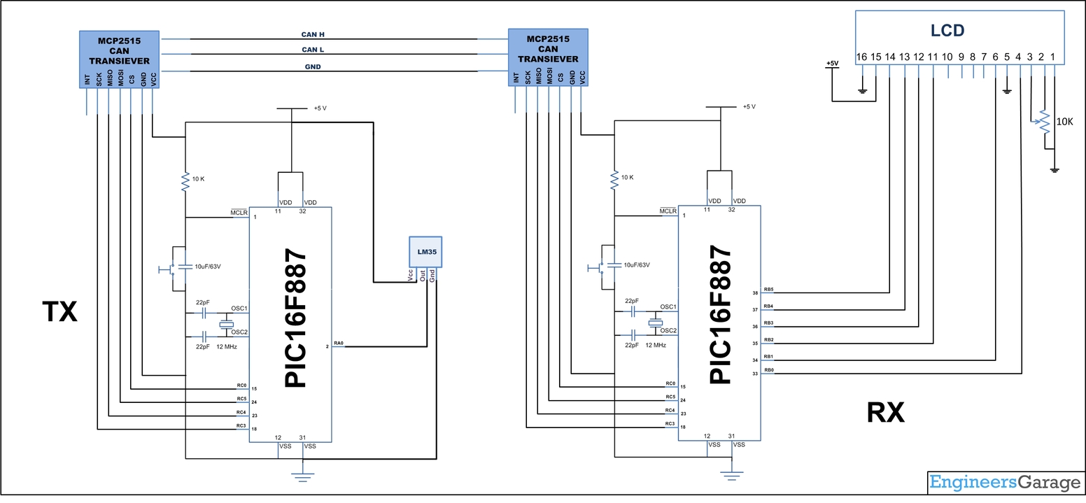
The following is a simple two-node CAN bus–based project. The block diagram of the project is shown in Figure. The system is made up of two CAN nodes. DISPLAY node that reads the temperature from the CAN Bus and displays it on an LCD. This process is repeated continuously. The other node called COLLECTOR node reads the temperature from an LM35 temperature sensor.

Fig. 3: Block Representation of PIC16F887 microcontroller interfacing on CAN bus
DISPLAY Processor:
DISPLAY processor consists of a PIC18F887 microcontroller with a MCP2515 CAN module and an TJA1040 transceiver chip. The PIC18F887 is operated from an 8MHz crystal. The MCLR input is connected to an external reset button. And MCP2515 has SPI interface which is used to connect using SPI pins in PIC16f887. The Pins CANH and CANL of the transceiver chip are connected to the CAN bus. LCD is connected to PORTB of the PIC18F887 to display the temperature values.
COLLECTOR Processor:
The COLLECTOR processor consists of a PIC18F887 microcontroller with a MCP2515 CAN module and an TJA1040 transceiver chip. The PIC18F887 is operated from an 8MHz crystal. The MCLR input is connected to an external reset button. LM35DZ-type semiconductor temperature sensor is connected to Analog input AN0 of the Microcontroller. The sensor generates an analog voltage directly proportional to the measured temperature, the output is 10mV/C. For example, at 20 degree Celcius the output voltage is 200mV. The CANH and CANL outputs of this chip are connected directly to a twisted cable terminating at the CAN bus. The TJA1040is an 8-pin chip that supports data rates up to 1Mb/s. The chip can drive up to 112 nodes. A reference voltage equal to VDD/2 is output from pin 5 of the chip.
The program listing is in two parts: the DISPLAY program and the COLLECTOR program.
For details about using MikroC to program pic controllers refer here.
The operation of the system is as follows:
-
The DISPLAY processor that waits for the current temperature message send from the COLLECTOR processor over the CAN bus.
-
The COLLECTOR processor measure the temperature, formats it, and sends to the DISPLAY processor over the CAN bus.
-
The DISPLAY processor reads the message from the CAN bus and then displays it on the LCD which is repeated every second.
Hardware assembly:

Fig. 4: Image of PIC16F887 Microcontroller based Receiver Circuit on One side of CAN Bus

Fig. 5: Prototype of PIC16F887 to PIC16F887 Communication over CAN Bus
You may also like:


Circuit Diagrams
Project Video
Filed Under: Electronic Projects, PIC
Filed Under: Electronic Projects, PIC

Questions related to this article?
👉Ask and discuss on EDAboard.com and Electro-Tech-Online.com forums.
Tell Us What You Think!!
You must be logged in to post a comment.