[[wysiwyg_imageupload:2163:]]The Project is contributed by Mr. Bharat Baravaliya
CIRCUIT ELEMENTS
capacitor banks, and other electrical loads.
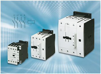
Operating Principle:
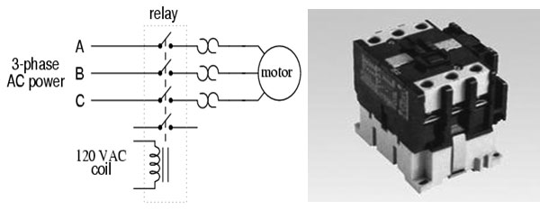
Components
3. Light-emitting diode:

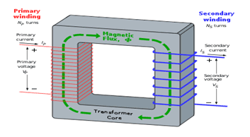
 where VS is the instantaneous voltage, NS is the number of turns in the secondary coil and ? equals the magnetic flux through one turn of the coil. If the turns of the coil are oriented perpendicular to the magnetic field lines, the flux is the product of the magnetic flux density B and the area A through which it cuts. The area is constant, being equal to the cross-sectional area of the transformer core, whereas the magnetic field varies with time according to the excitation of the primary. Since the same magnetic flux passes through both the primary and secondary coils in an ideal transformer, the instantaneous voltage across the primary winding equals

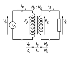 The ideal transformer as a circuit element
 . This relationship is reciprocal, so that the impedance ZP of the primary circuit appears to the secondary to be
Practical Considerations:
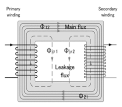
The ideal transformer model assumes that all flux generated by the primary winding links all the turns of every winding, including itself. In practice, some flux traverses paths that take it outside the windings. Such flux is termed leakage flux, and results in leakage inductance in series with the mutually coupled transformer windings.
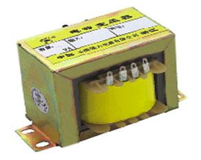
The transformer winding high-voltage connection points are typically labeled as H1, H2 (sometimes H0 if it is internally grounded) and X1, X2, and sometimes an X3 tap may be present. Sometimes a second isolated winding (Y1, Y2, Y3) may also be available on the same voltage transformer. The high side (primary) may be connected phase to ground or phase to phase. The low side (secondary) is usually phase to ground.
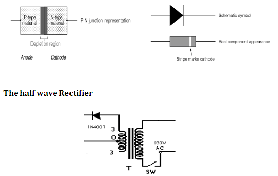
Transformer + Rectifier:

The varying DC output is suitable for lamps, heaters and standard motors. It is not suitable for electronic circuits unless they include a smoothing capacitor
Types:

PCB FABRICATION
WORKING
Project Source Code
Circuit Diagrams
Project Datasheet
Filed Under: Electronic Projects


Questions related to this article?
👉Ask and discuss on EDAboard.com and Electro-Tech-Online.com forums.
Tell Us What You Think!!
You must be logged in to post a comment.