It is very much easy to get familiar with this circuit.
As this circuit is consist of minimum amount of components
Also making cost of this circuit is too low.
This circuit is made just for fun, not to harm anyone.
This circuit produces a tick-tick sound. This sound is just similar with the loud clicking clock which is mainly attached with the time bomb.
This circuit is constructed with the help of 555 timer.Astable mode of the IC is employed in “Tic-Tic bomb”.
This circuit is developing to produce tic-tic sound, this sound is same as the clock connected with the time-bomb produces. With the help of this circuit you can scared your friends, family members or any of your known ones just for fun and not for harming them.
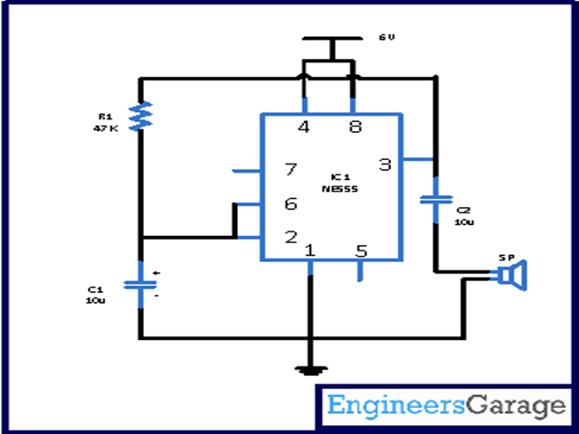
In this circuit 555 timer IC is connected in the astable mode. This circuit works on 6V. Pin 4 and 8 is used to provide power while pin 1 of the IC is ground. Pin 5 and 7 of the IC is unused in this circuit. Pin 2 and 6 is used to give input while from pin 3 of the IC output is taken.
Now when the power is given in the circuit IC driven into the astable mode. And this will generate a square wave series in the output. The charging as well as discharging of C2 is rest on the square wave. Now this charging and discharging of C2 flows a current which we hear from a speaker sp as a tick sound for each wave length. With the support of the resistance R1 and capacitor C1 output frequency of the waves are determined. In this circuit it is attached to generate clock-like rate.
For slowing the ticking rate you can increase the value of the capacitor C1 while for speeding up the ticking sound you can decrease the value of C1.
We have designed this circuit using the breadboard. If you want to can design the circuit in pcb or you can solder the circuit.
Circuit Diagrams
Project Components
Filed Under: Electronic Projects

Questions related to this article?
👉Ask and discuss on Electro-Tech-Online.com and EDAboard.com forums.
Tell Us What You Think!!
You must be logged in to post a comment.