Engineers Garage

  • Electronics Projects and Tutorials
    • Electronic Projects
      • Arduino Projects
      • AVR
      • Raspberry pi
      • ESP8266
      • BeagleBone
      • 8051 Microcontroller
      • ARM
      • PIC Microcontroller
      • STM32
    • Tutorials
      • Audio Electronics
      • Battery Management
      • Brainwave
      • Electric Vehicles
      • EMI/EMC/RFI
      • Hardware Filters
      • IoT tutorials
      • Power Tutorials
      • Python
      • Sensors
      • USB
      • VHDL
    • Circuit Design
    • Project Videos
    • Components
  • Articles
    • Tech Articles
    • Insight
    • Invention Stories
    • How to
    • What Is
  • News
    • Electronic Product News
    • Business News
    • Company/Start-up News
    • DIY Reviews
    • Guest Post
  • Forums
    • EDABoard.com
    • Electro-Tech-Online
    • EG Forum Archive
  • DigiKey Store
    • Cables, Wires
    • Connectors, Interconnect
    • Discrete
    • Electromechanical
    • Embedded Computers
    • Enclosures, Hardware, Office
    • Integrated Circuits (ICs)
    • Isolators
    • LED/Optoelectronics
    • Passive
    • Power, Circuit Protection
    • Programmers
    • RF, Wireless
    • Semiconductors
    • Sensors, Transducers
    • Test Products
    • Tools
  • Learn
    • eBooks/Tech Tips
    • Design Guides
    • Learning Center
    • Tech Toolboxes
    • Webinars & Digital Events
  • Resources
    • Digital Issues
    • EE Training Days
    • LEAP Awards
    • Podcasts
    • Webinars / Digital Events
    • White Papers
    • Engineering Diversity & Inclusion
    • DesignFast
  • Guest Post Guidelines
  • Advertise
  • Subscribe

Time Division Multiplexing: Hardware Implementation

By Soham Chetan Kamani April 21, 2008


Have you ever wondered how thousands of people make phone calls and communicate at the same time, yet there are only 4 wires on each telephone pole, that accommodate all these calls. We all know that the is one wire to our house and one to the house of the person we want to call, but how is it possible that our lines and the lines of every other person living in our neighbourhood, all send information through only one common line, and furthermore, how is everyones information received simultaneously at the other end?

The answer lies in a simple concept called time division multiplexing. Although modern telecommunication networks use much faster and more efficient methods, time division multiplexing or TDM for short was an important communication technique in older days, and can still be used effectively for small networks.
This tutorial is going to take you through the main concept involved in TDM and also show you how you can implement it using hardware .
Principle of TDM
Image demonstrating principle of Time Division Multiplexing
Fig. 1: Image demonstrating principle of Time Division Multiplexing
As we can see in the above diagram, all bits are fed into a common multiplexor, after which they get transmitted on a single transmission line to a demultiplexor, which delivers the respective bits the recipients. The main idea here is that the multiplexor and demultiplexor are both timed at the sam time, i.e. the selector lines of the multiplexor and demultiplexor are given the same values at the same, short interval of time. Suppose there are equally spaced times t1,t2,t3,t4. Then from time t1 up till time t2,the selectors of the mux and demux are given 000 input, so the first bit is transmitted. Similarly between t2 and t3, the second bit is transmitted, and the third bit between t3 and t4.the important factor here is the interval of time, which must be less than half of the time period of either of the signals giving bit1 bit2 or bit3 (See nyquist criterion )
Hardware Implementation
There are a number of ways to implement TDM in terms of hardware. The most direct way is to use a multiplexor and a demultiplexor and use a timing circuit to give the selector pins the inputs. However we are going to use a different approach, which uses the arduino as a timing circuit as well as a demux. This decreases the probability of error in the output, makes it easier for us to observe the output on a serial monitor and also removes an entire IC from the circuit, making the soldering and connecting much easier.
Components required
      1.      LEDs   x8
      2.      300ohm resistor x8
       3.      IC 74150 mux
       4.      8-bit DIP switch          
       5.      Arduino microcontroller board
       6.      Connecting wires and jumper cables
Working principle
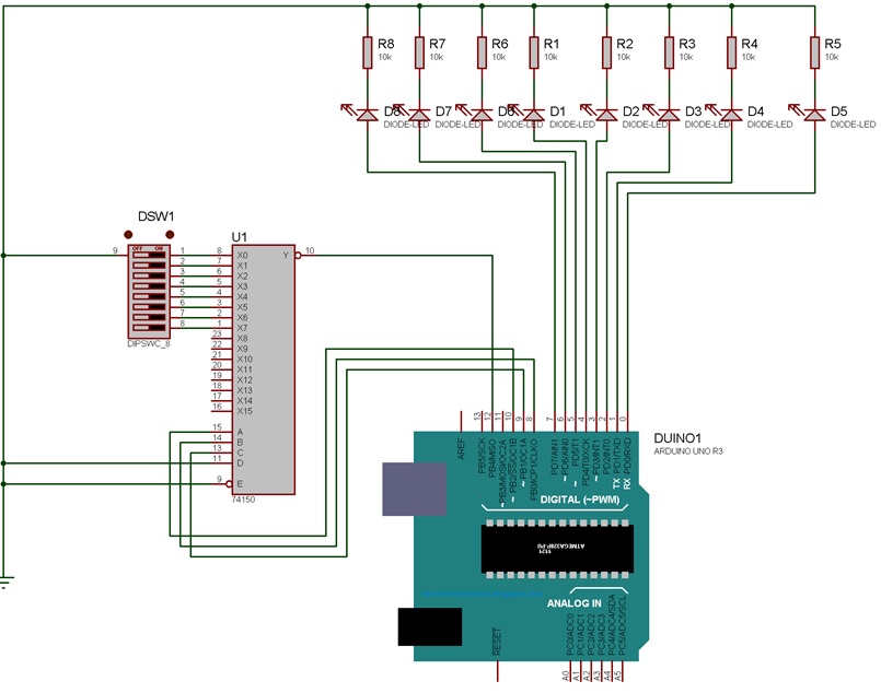
       1.      The arduino gives binary values from 000 till 111 through its pins into the selector pins of the mux.
       2.      The selector pin D is always kept at LOW because we only consider the first 8 outputs.
       3.      The input region of the mux is connected to the 8bit DIP switch which selects the input, the other end being connected to ground.
        4.      The strobe and enable are also connected to ground, as per the datasheet of 74150
       5.      The binary values of the arduino change at a fixed time interval. The output on that time interval from the mux is fed to the arduino and it is in turn applied to the respective LED.thus at the next time interval the input value at the next pin of the mux is fed to the next LED.
      6.      Therefore the only output wire from the mux is also the only input wire to the arduino. Thus all the 8bit information is fed simultaneously to the arduino through one wire, thus demonstrating TDM successfully.

 Process and Output Images

Procedure and Guidelines
       ·         Make the circuit according to the circuit diagram
       ·         It is suggested the the 5v pin present in the arduino is used as the power source to the multiplexor.
       ·         The circuit is best constructed in a PCB, or otherwise soldered onto a perf board.
       ·         If solder is used, remember to always use an IC socket to make the IC connections first, as soldering the IC directly will damage it.
       ·         Instead of using 8 separate resistors for each LED , you can use a single common 300ohm resistor for simplicity
       ·         Since pin0 and pin1 of the arduino are also its Rx and Tx pins, used for serial communication, you might experience interference in output for the first two LEDs, but this is normal. If you wish to obtain a better output, disable the serial communication on the arduino. However, you won’t be able to observe the output on the serial monitor if you choose this option.
       ·         After all the connections are made and verified, flash the program code on to the arduino using the arduino software.
Prototype of Arduino Based Time Division Multiplexer
            Fig. 2: Prototype of Arduino Based Time Division Multiplexer
 
Image of Arduino based Time Division Multiplexer
              Fig. 3: Image of Arduino based Time Division Multiplexer
 
Image showing output of Time Division Multiplexing with the help of LEDs
          Fig. 4: Image showing output of Time Division Multiplexing with the help of LEDs


Project Source Code

###

int bit2=9;
int bit1=8;
int bit0=10;
void setup(){
  
  Serial.begin(9600);
  pinMode(8,OUTPUT);
  pinMode(9,OUTPUT);
  pinMode(10,OUTPUT);
  pinMode(12,INPUT);
  pinMode(2,OUTPUT);
  pinMode(3,OUTPUT);
  pinMode(4,OUTPUT);
  pinMode(5,OUTPUT);
  pinMode(6,OUTPUT);
  pinMode(7,OUTPUT);
}
void loop(){
  digitalWrite(bit2,LOW);
  digitalWrite(bit1,LOW);
  digitalWrite(bit0,LOW);
  Serial.print(digitalRead(12));
  digitalWrite(7,digitalRead(12));
  delay(10);
  //--------------------------
  digitalWrite(bit2,LOW);
  digitalWrite(bit1,LOW);
  digitalWrite(bit0,HIGH);
  Serial.print(digitalRead(12));
  digitalWrite(6,digitalRead(12));
  delay(10);
  //--------------------------
  digitalWrite(bit2,LOW);
  digitalWrite(bit1,HIGH);
  digitalWrite(bit0,LOW);
  Serial.print(digitalRead(12));
  digitalWrite(5,digitalRead(12));
  delay(10);
  //--------------------------
  digitalWrite(bit2,LOW);
  digitalWrite(bit1,HIGH);
  digitalWrite(bit0,HIGH);
  Serial.print(digitalRead(12));
  digitalWrite(4,digitalRead(12));
  delay(10);
  //--------------------------
  digitalWrite(bit2,HIGH);
  digitalWrite(bit1,LOW);
  digitalWrite(bit0,LOW);
  Serial.print(digitalRead(12));
  digitalWrite(3,digitalRead(12));
  delay(10);
  //--------------------------
  digitalWrite(bit2,HIGH);
  digitalWrite(bit1,LOW);
  digitalWrite(bit0,HIGH);
  Serial.print(digitalRead(12));
  digitalWrite(2,digitalRead(12));
  delay(10);
  //--------------------------
  digitalWrite(bit2,HIGH);
  digitalWrite(bit1,HIGH);
  digitalWrite(bit0,LOW);
  Serial.print(digitalRead(12));
  delay(10);
  //--------------------------
  digitalWrite(bit2,HIGH);
  digitalWrite(bit1,HIGH);
  digitalWrite(bit0,HIGH);
  Serial.println(digitalRead(12));
  delay(10);
  //--------------------------
  
}

###


Circuit Diagrams

Circuit-Diagram-Arduino-Based-Time-Division-Multiplexing-Prototype


Filed Under: Electronic Projects
Tagged With: tdm, time division multiplexing
 

Next Article

← Previous Article
Next Article →

Questions related to this article?
👉Ask and discuss on EDAboard.com and Electro-Tech-Online.com forums.


Tell Us What You Think!! Cancel reply

You must be logged in to post a comment.

EE TECH TOOLBOX

“ee
Tech Toolbox: Internet of Things
Explore practical strategies for minimizing attack surfaces, managing memory efficiently, and securing firmware. Download now to ensure your IoT implementations remain secure, efficient, and future-ready.

EE Learning Center

EE Learning Center
“engineers
EXPAND YOUR KNOWLEDGE AND STAY CONNECTED
Get the latest info on technologies, tools and strategies for EE professionals.

HAVE A QUESTION?

Have a technical question about an article or other engineering questions? Check out our engineering forums EDABoard.com and Electro-Tech-Online.com where you can get those questions asked and answered by your peers!


RSS EDABOARD.com Discussions

  • SPI speed pic18f66j15
  • I/O constraint for Hold check
  • Inverting OpAmp - basic circuit question
  • Why does Synopsys DC need Inverters and Buffers if my RTL only has XOR logic?
  • GanFet power switch starts burning after 20 sec

RSS Electro-Tech-Online.com Discussions

  • LED circuit for 1/6 scale diorama
  • stud mount Schottky diodes
  • Hi Guys
  • Precision CAD Drafting Services for Architectural & Engineering Projects
  • using a RTC in SF basic

Featured – Designing of Audio Amplifiers part 9 series

  • Basics of Audio Amplifier – 1/9
  • Designing 250 Milli Watt Audio Power Amplifier – 2/9
  • Designing 1 Watt Audio Power Amplifier – 3/9
  • Designing a Bass Boost Amplifier – 4/9
  • Designing a 6 Watt Car Audio Amplifier – 5/9
  • Design a low power amplifier for headphones- 6/9

Recent Articles

  • Fischer connector system adds ratchet locking system designed for 300g shock resistance
  • Littelfuse introduces tactile switch with enhanced bracket peg design for mounting strength
  • Infineon releases GaN switch with monolithic bidirectional design
  • Sienna Semiconductor data converters feature sample rates from 20 to 250 Msps
  • Delta’s 5,500 W power supplies achieve 97.5% energy efficiency for AI servers

EE ENGINEERING TRAINING DAYS

engineering

Submit a Guest Post

submit a guest post
Engineers Garage
  • Analog IC TIps
  • Connector Tips
  • Battery Power Tips
  • DesignFast
  • EDABoard Forums
  • EE World Online
  • Electro-Tech-Online Forums
  • EV Engineering
  • Microcontroller Tips
  • Power Electronic Tips
  • Sensor Tips
  • Test and Measurement Tips
  • 5G Technology World
  • Subscribe to our newsletter
  • About Us
  • Contact Us
  • Advertise

Copyright © 2025 WTWH Media LLC. All Rights Reserved. The material on this site may not be reproduced, distributed, transmitted, cached or otherwise used, except with the prior written permission of WTWH Media
Privacy Policy

Search Engineers Garage

  • Electronics Projects and Tutorials
    • Electronic Projects
      • Arduino Projects
      • AVR
      • Raspberry pi
      • ESP8266
      • BeagleBone
      • 8051 Microcontroller
      • ARM
      • PIC Microcontroller
      • STM32
    • Tutorials
      • Audio Electronics
      • Battery Management
      • Brainwave
      • Electric Vehicles
      • EMI/EMC/RFI
      • Hardware Filters
      • IoT tutorials
      • Power Tutorials
      • Python
      • Sensors
      • USB
      • VHDL
    • Circuit Design
    • Project Videos
    • Components
  • Articles
    • Tech Articles
    • Insight
    • Invention Stories
    • How to
    • What Is
  • News
    • Electronic Product News
    • Business News
    • Company/Start-up News
    • DIY Reviews
    • Guest Post
  • Forums
    • EDABoard.com
    • Electro-Tech-Online
    • EG Forum Archive
  • DigiKey Store
    • Cables, Wires
    • Connectors, Interconnect
    • Discrete
    • Electromechanical
    • Embedded Computers
    • Enclosures, Hardware, Office
    • Integrated Circuits (ICs)
    • Isolators
    • LED/Optoelectronics
    • Passive
    • Power, Circuit Protection
    • Programmers
    • RF, Wireless
    • Semiconductors
    • Sensors, Transducers
    • Test Products
    • Tools
  • Learn
    • eBooks/Tech Tips
    • Design Guides
    • Learning Center
    • Tech Toolboxes
    • Webinars & Digital Events
  • Resources
    • Digital Issues
    • EE Training Days
    • LEAP Awards
    • Podcasts
    • Webinars / Digital Events
    • White Papers
    • Engineering Diversity & Inclusion
    • DesignFast
  • Guest Post Guidelines
  • Advertise
  • Subscribe