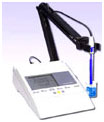
Some Microcontroller based Laboratory instruments such as Digital balance, pH Meter etc have rechargeable battery inside. This inbuilt battery should be properly charged for the error free operation of these instruments. If the instrument is not using (or charging) for long time, its inbuilt battery will be destroyed permanently. This charger timer circuit helps to keep the battery in top condition through automatic charging for 5 to 6 hours daily so that the instrument can be left unattended. The battery will be charged only during the day time.

The advantages of this circuit are
1. Prevents over charging of battery
2. Saves power
3. Gives sufficient time to complete the chemical reaction between the charging cycles
4. Helps to keep the battery in the unattended mode of charging.
Many lab instruments are supplied with a 6 or 12 volt DC adapter for charging theinbuilt battery. This adapter can be plugged in to the AC socket connected to the relay of the circuit. So when the relay turns on, the adapter gets power supply to charge the battery.
The timer circuit is built around the binary counter IC CD4060 with an LDR control for day time operation. When the LDR is in light, it conducts and the reset pin 12 of IC1 will be grounded. IC then starts oscillating with C1 and R2. After 1 hour, the Q12output of IC1 turns high and energizes the relay through T1. The phase line is connected to the common contact of relay so that when the relay energize, it gives power to the AC socket through the NO (Normally Open) contact. Q12 output turns low after 1 hourand again turns on after 1 hour. In this way, total 5-6 times, the relay turns on during the day time.

Since the instrument is battery operated, it can be used as usual by keeping the charger in the socket.
Green LED indicates the Active mode and the Red LED indicates the Charging mode.
It is better to limit the charging to 2-3 hours daily if the instrument is not in use. For this, adjust the sensitivity of LDR through VR1 so that the circuit becomes active only when the room light is high.
Circuit Diagrams
Filed Under: Electronic Projects


Questions related to this article?
👉Ask and discuss on EDAboard.com and Electro-Tech-Online.com forums.
Tell Us What You Think!!
You must be logged in to post a comment.