The tone generator's function is to produce different frequency sine wave for each digital word applied to its input. This project allows the computer to sweep the instrument under test through the desired frequency range. It can be adapted to create a Morse code circuit, by adding a switch to the output. The tone generator circuit described here is based upon 555 as a free running multivibrator. Shown below is internal structure of a multivibrator IC and its circuitry.
[[wysiwyg_imageupload:7733:]]
Fig. 1: Circuit Diagram For Multivibrator IC
This tone generator circuit is based on 555 timers, working as a free running oscillator. The frequency or pitch of the tone is set by the resistors and capacitors situated in the left side of the circuit. The capacitor is used to reduce noise or undesired signals for smooth operation of potentiometer.
The tone generator overturns and buffers 8 data lines from the computer. By the use of a D/A (digital to analog) converter and a current to voltage converter, the digital word is converted to a D.C. voltage. An 8-bit frequency control word is used here as it allows 256 frequencies to be selected.
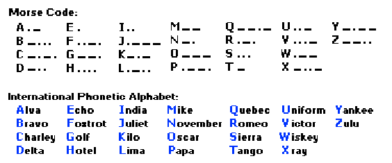
Here we are presenting some Morse code for the reference so as to generate it just by adding a switch to circuit described above.

Fig. 2: Image Showing Morse Code
Circuit Diagrams
Project Components
Filed Under: 555 Timers, Electronic Projects


Questions related to this article?
👉Ask and discuss on EDAboard.com and Electro-Tech-Online.com forums.
Tell Us What You Think!!
You must be logged in to post a comment.