Engineers Garage

  • Projects and Tutorials
    • Electronic Projects
      • 8051
      • Arduino
      • ARM
      • AVR
      • PIC
      • Raspberry pi
      • STM32
    • Tutorials
    • Circuit Design
    • Project Videos
    • Components
  • Articles
    • Tech Articles
    • Insight
    • Invention Stories
    • How to
    • What Is
  • News
    • Electronic Products News
    • DIY Reviews
    • Guest Post
  • Forums
    • EDABoard.com
    • Electro-Tech-Online
    • EG Forum Archive
  • Digi-Key Store
    • Cables, Wires
    • Connectors, Interconnect
    • Discrete
    • Electromechanical
    • Embedded Computers
    • Enclosures, Hardware, Office
    • Integrated Circuits (ICs)
    • Isolators
    • LED/Optoelectronics
    • Passive
    • Power, Circuit Protection
    • Programmers
    • RF, Wireless
    • Semiconductors
    • Sensors, Transducers
    • Test Products
    • Tools
  • EE Resources
    • DesignFast
    • LEAP Awards
    • Oscilloscope Product Finder
    • White Papers
    • Webinars
  • EE Learning Center
    • Design Guides
      • WiFi & the IOT Design Guide
      • Microcontrollers Design Guide
      • State of the Art Inductors Design Guide
  • Women in Engineering

Traffic light(using NE555)

By Ashutosh Bhatt

Traffic signals are used to control the traffic on the road, so to avoid accidents and jams. Working of this project is not anyway different from traffic indicators we noticed on the roads. We construct this circuit with the help of well-known IC i.e. NE555. Control signal in this circuit is mainly three LED i.e. red, green and yellow.

  This circuit is low cost circuit as it used minimum amount of components. Also assembling of the circuit is too easy to do.


Basic building block of this circuit is IC NE555 and LEDs along with capacitors and resistors as supporting components.LED1 (red in colour) has identical amount of on and off time. Just before the stop of LED1, LED2 (yellow in colour) glows for a very short period of time after that LED3 will glow. IC2 gets the power from the IC1, this brightens the LED3 (green in colour).And as soon as IC2 alter the state LED3 switch off and LED 1 starts blink.

This circuit needs 12V of supply to work. While the second IC (IC2) gets 2V less supply than the actual given.

IC1 as well as IC2 both are connected like a oscillator which will work in the astable mode. Till the time both IC get supply they will oscillate for all that duration of time. But IC2 will not get power for all the time. As soon as the power is given IC1 turns on but C1 is not charged which in turns output at pin 3 at high. As a consequence of it LED1 will not blink. But this output will send to IC2 and IC2 turns on.

LED3 will start brighten as its gets high voltage from the IC2 pin3.And capacitor C2 charged by the 2/3 of the applied voltage due to which IC2 changes its state and LED3 stops glowing. And LED1 starts glowing as C2 begins to discharge but C1 begin charging by the help of R1 and pin3 of IC1 reaches to low state. LED2 will glow just before LED3 glow. Capacitor C2 is used in the circuit so that LED2 will remain glow for short duration only.

 Underground secret for the long cycle-time of IC1 is R1 while IC2 short cycle is due to R3.
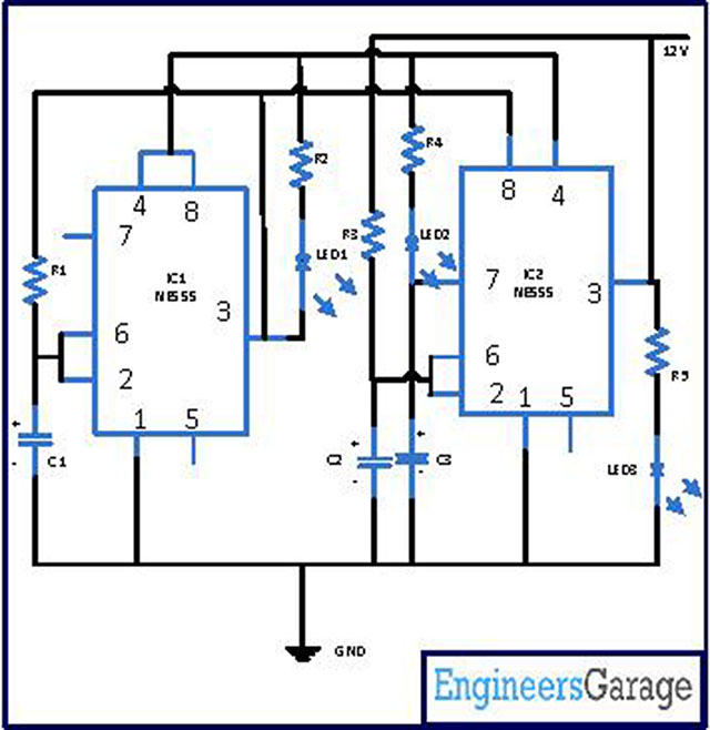
Circuit Diagrams

Traffic-light-using-NE555Page-1

Project Components

  • 555 Timer IC
  • Capacitor
  • LED
  • Resistor


Filed Under: Electronic Projects


Questions related to this article?
👉Ask and discuss on Electro-Tech-Online.com and EDAboard.com forums.


Tell Us What You Think!! Cancel reply

You must be logged in to post a comment.

HAVE A QUESTION?

Have a technical question about an article or other engineering questions? Check out our engineering forums EDABoard.com and Electro-Tech-Online.com where you can get those questions asked and answered by your peers!


Featured Tutorials

  • PS2 Keyboard To Store Text In SD Card Using Arduino Circuit Setup On Breadboard
    How To Use PS2 Keyboard To Store Text In SD Card Using Arduino- (Part 42/49)
  • Wireless Path Tracking System Using Mouse, XBee And Arduino Circuit Setup On Breadboard
    How To Make A Wireless Path Tracking System Using Mouse, XBee And Arduino- (Part 43/49)
  • How to Make a Wireless Keyboard Using Xbee with Arduino- (Part 44/49)
  • Making Phone Call From GSM Module Using Arduino Circuit Setup On Breadboard
    How to Make Phonecall From GSM Module Using Arduino- (Part 45/49)
  • How to Make a Call using Keyboard, GSM Module and Arduino
    How To Make A Call Using Keyboard, GSM Module And Arduino- (Part 46/49)
  • Receiving SMS Using GSM Module With Arduino Prototype
    How to Receive SMS Using GSM Module with Arduino- (Part 47/49)

Stay Up To Date

Newsletter Signup

Sign up and receive our weekly newsletter for latest Tech articles, Electronics Projects, Tutorial series and other insightful tech content.

EE Training Center Classrooms

EE Classrooms

Recent Articles

  • Renesas delivers intelligent sensor solutions for IoT applications
  • Microchip Technology releases AVR-IoT Cellular Mini Development Board
  • Qualcomm acquires Cellwize to accelerate 5G adoption and spur infrastructure innovation
  • MediaTek’s chipset offers high-performance option for 5G smartphones
  • Nexperia’s new level translators support legacy and future mobile SIM cards

Most Popular

5G 555 timer circuit 8051 ai Arduino atmega16 automotive avr bluetooth dc motor display Electronic Part Electronic Parts Fujitsu ic infineontechnologies integratedcircuit Intel IoT ir lcd led maximintegratedproducts microchip microchiptechnology Microchip Technology microcontroller microcontrollers mosfet motor powermanagement Raspberry Pi remote renesaselectronics renesaselectronicscorporation Research samsung semiconductor sensor software STMicroelectronics switch Technology vishayintertechnology wireless

RSS EDABOARD.com Discussions

  • Using LTspice to check Current sense transformer reset?
  • Plotting E_theta and E_phi using the fields calculator in HFSS
  • SRF04 module measure distance
  • Motherboard - worst case scenario
  • Will Wifi throughput be affected by RSSI (attenuation) in my setup?

RSS Electro-Tech-Online.com Discussions

  • Are Cross-wind compensation and Road crown compensation functions inputs to LKA function?
  • Interfacing ZMOD4410 with Arduino UNO
  • Help diagnosing a coffee maker PCB
  • Capacitor to eliminate speaker hum
  • Identify a circuit.
Engineers Garage
  • Analog IC TIps
  • Connector Tips
  • DesignFast
  • EDABoard Forums
  • EE World Online
  • Electro-Tech-Online Forums
  • Microcontroller Tips
  • Power Electronic Tips
  • Sensor Tips
  • Test and Measurement Tips
  • 5G Technology World
  • About Us
  • Contact Us
  • Advertise

Copyright © 2022 WTWH Media LLC. All Rights Reserved. The material on this site may not be reproduced, distributed, transmitted, cached or otherwise used, except with the prior written permission of WTWH Media
Privacy Policy | Advertising | About Us

Search Engineers Garage

  • Projects and Tutorials
    • Electronic Projects
      • 8051
      • Arduino
      • ARM
      • AVR
      • PIC
      • Raspberry pi
      • STM32
    • Tutorials
    • Circuit Design
    • Project Videos
    • Components
  • Articles
    • Tech Articles
    • Insight
    • Invention Stories
    • How to
    • What Is
  • News
    • Electronic Products News
    • DIY Reviews
    • Guest Post
  • Forums
    • EDABoard.com
    • Electro-Tech-Online
    • EG Forum Archive
  • Digi-Key Store
    • Cables, Wires
    • Connectors, Interconnect
    • Discrete
    • Electromechanical
    • Embedded Computers
    • Enclosures, Hardware, Office
    • Integrated Circuits (ICs)
    • Isolators
    • LED/Optoelectronics
    • Passive
    • Power, Circuit Protection
    • Programmers
    • RF, Wireless
    • Semiconductors
    • Sensors, Transducers
    • Test Products
    • Tools
  • EE Resources
    • DesignFast
    • LEAP Awards
    • Oscilloscope Product Finder
    • White Papers
    • Webinars
  • EE Learning Center
    • Design Guides
      • WiFi & the IOT Design Guide
      • Microcontrollers Design Guide
      • State of the Art Inductors Design Guide
  • Women in Engineering